Inside Spacewar!
Part 5: Maneuvering in Space
(Introduction · The Code · Reading Input · Scanning the Control Word · Rotation and Thrust · Updating Positions · The Basic Trick · Putting it on the Scope · Fire! · Last Checks: Jumping to Hyperspace · Variations · The Original Control Boxes)
Once again it's Spacewar! time. In this part of our journey through the internals of Spacewar! we're going to explore one of the game's object routines, namely the one for maneuvering and handling ships. So, this is about the "nautical" part of the game. Most of the code, we'll see here, is by Steve Russell, but some bits may be by others who were lending a helping hand, especially by Robert A. Saunders (cf. Levy, Steven, Hackers — Heroes of the Computer Revolution; 1984/2010, p. 51).
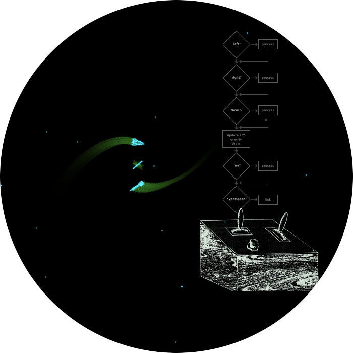
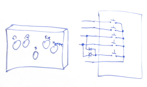
Spaceships and maneuvering code in Spacewar!
Credits: Drawing of control box by J.M. Graetz 1981; Screen-shot (emulation) and montage: N. Landsteiner 2014
BTW: ▶ You can play here the original code of Spacewar! running in an emulation.
As usual, we'll start with a look at the code involved in its entirety, just to get a picture of it. And as usual, we won't do so, without including the standard credits first:
Spacewar! was conceived in 1961 by Martin Graetz, Stephen Russell, and Wayne Wiitanen. It was first realized on the PDP-1 in 1962 by Stephen Russell, Peter Samson, Dan Edwards, and Martin Graetz, together with Alan Kotok, Steve Piner, and Robert A Saunders. Spacewar! is in the public domain, but this credit paragraph must accompany all distributed versions of the program.
The Code
	/ spaceship calc

ss1,	dap srt		/ first spaceship
	jsp i \cwg
	dio \scw
	jmp sr0

ss2,	dap srt		/ second spaceship
	jsp i \cwg
	rir 4s
	dio \scw

sr0,
sc1,	lio \scw		/control word
	clf 6 cla-opr	/update angle
	spi
	add maa
	ril 1s
	spi
	sub maa
mom,	add .
	dac i mom
	szs 10
	jmp sr8
	dzm i mom
	ral 7s
sr8,	ril 1s
	spi
	stf 6
	lio i \mfu
	spi i
	clf 6

mth,	add .
	sma
	sub (311040
	spa
	add (311040
	dac i mth
	jda sin
	dac \sn
	dzm \bx
	dzm \by
	szs 60
	jmp bsg
	lac i mx1
	sar 9s
	sar 2s
	dac \t1
	jda imp
	lac \t1
	dac \t2
	lac i my1
	sar 9s
	sar 2s
	dac \t1
	jda imp
	lac \t1
	add \t2
	sub str
	sma i sza-skp
	jmp pof
	add str

//	snip, gravity code here

bsg,	cla
	sad i \mfu
	clf 6
	lac i mth
	jda cos
	dac \cs
	sar 9s
	xct sac
	szf i 6
	cla
	add \by
	diff \mdy, my1, (sar 3s
	lac \sn
	sar 9s
	xct sac
	cma
	szf i 6
	cla
	add \bx
	diff \mdx, mx1, (sar 3s
sp1,	scale \sn, 5s, \ssn
sp2,	scale \cs, 5s, \scn
	lac i mx1

	sub \ssn
	dac \sx1
	sub \ssn
	dac \stx
	lac i my1
	add \scn
	dac \sy1
	add \scn
	dac \sty
	scale \sn, 9s, \ssn
	scale \cs, 9s, \scn
	lac \ssn
	dac \ssm
	add \scn
	dac \ssc
	dac \ssd
	lac \ssn
	sub \scn
	dac \csn
	cma
	dac \csm
	lac \scn
	dac \scm
	cla cli-opr
	dpy-4000
sp5,	jmp .
sq6,	ioh
	ranct sar 9s, sar 4s, \src
	lio \scw
	ril 2s
	spi i 		/ not blasting
	jmp sq9		/ no tail
sq7,	scale \sn, 8s, \ssn
	scale \cs, 8s, \scn
	count i \mfu, st2
	dzm i \mfu
	jmp sq9

st2,	yincr \sx1, \sy1, sub
	dispt i, \sy1
	count \src,sq7
sq9,	count i ma1, sr5	/ check if torp tube reloaded
	dzm i ma1	/ prevent count around
mco,	lac .		/ previous control word
	cma
	szs i 30
	clc
	and \scw	/ present control word
	ral 3s		/ torpedo bit to bit 0
	sma
	jmp sr5		/ no launch
	count i \mtr, st1	/ check if torpedos exhausted
	dzm i \mtr		/ prevent count around
	jmp sr5
st1,	init sr1, mtb	/ search for unused object
sr1,	lac .
	sza i		/ 0 if unused
	jmp sr2
	index sr1, (lac mtb nob, sr1
	hlt		/ no space for new objects
	jmp .-1

//	snip, torpedo setup routine

sr5,	count i \mh3, st3	/ hyperbutton active?
	dzm i \mh3
	lac i \mh2
	sza i
	jmp st3
	lac \scw
	cma
	ior i mco
	and (600000
	sza
	jmp st3
	lac i ml1
	dac i \mh1
	lac (hp1 400000
	dac i ml1
	xct hd1
	dac i ma1
	law 3
	dac i mb1
st3,
srt,	jmp .
(Code as in version 3.1. For the basics of PDP-1 instructions and Macro assembler code, please refer to Part 1. We'll repeat the semantics of the instructions as we're encountering them.)
Let's see what's happening here. As we may recall from Part 3, when we were exploring the main loop or "object loop" of the program, we would end at label ss1 for spaceship #1 or ss2 for spaceship #2, when this was called as at label mq4 near the end of the main loop:
mq4,	lac i ml1	/ routine for calculating spaceship
	dap . 1		/ or other object and displaying it
	jsp .
As we also may remember, ml1 contains the address of the routine handling the current object (for a spaceship in cruise mode ss1 or ss2) and a sign-bit set to indicate the collidible state of the object. While this sign-bit was handy for the comparison loop, we must now get rid of it in order to make a regular jump to this subroutine. For this, we first load the actual address into the accumulator (mind the i- or defer bit used to load not the contents of ml1, but rather to use this for another address lookup). Then, the next instruction puts just the address part of this into the location immediately following to this, leaving the instruction part (the opcode jsp) as-is. Finally, this newly assembled instruction is executed and the program dispatches either to subroutine ss1 for spaceship 1 or ss2 for spaceship 2:
ss1,	dap srt		/ first spaceship  // deposit return address
	jsp i \cwg	// get control input
	dio \scw	// store it in \scw
	jmp sr0		// jump to sr0

ss2,	dap srt		/ second spaceship
	jsp i \cwg	// get control input
	rir 4s		// rotate IO right 4 bits
	dio \scw	// store it in \scw

sr0, ...
(As usual, comments starting with double slashes are mine and not in the original code.)
Besides suffering a gory violation of Spacewar!'s naming conventions by storing the return address in label srt (instead of a label srx — there is no srx at all — rather alluding to return by the charcters "rt"), this is loading the current control word or user input into the IO register by calling the reading routine aliased in variable \cwg (as in control word get(ter)) and stores it in variable \scw.
Reading Control Input
We've alreade seen (in Part 3) how this was set up at the very start of the program, either by using the default start address of 4 for the control boxes (designed by Bob Saunders and Alan Kotok) or by starting the program at location 5 for use with the test word switches at the PDP-1's control console. So this is either executing the getter subroutine at mg1 for the control boxes or the code at mg2 for the test word input:
mg1,	dap mg3		// deposit return address
	cli		// clear IO
	iot 11		// read control input into IO
mg3,	jmp .		// return

mg2,	dap mg4		// deposit return address
	lat		// load test word into AC
	swap		// exchange AC and IO (test word now in IO)
mg4,	jmp .		// return
Both are first depositing the return address, are then putting the reading in the IO register and jump to the deposited return address, the important difference being the code in between:
The first one is clearing the IO register (by the cli instruction) and is then loading the control word into it by the "iot 11" instruction. This instruction code is entirely undocumented, but we may reconstruct its working from this: The iot opcode is generally addressing the I/O-ports of the PDP-1 with the addressed device specidfied by the two lowest octal digits. Apparently device-code 11 is importing a reading from the flip-flops of switch-bay 1 of the PDP-1, where the control boxes would have been attached to. We may also infer from this particular code that this might have been imported by performing a logical OR, else there wouldn't have been the need to clear the IO register first.
The second one is using the lat instruction to load the state of the test word into the accumulator. Since we would want to abstract both readings into a single form, we've to move this into the IO register, just like the reading of the control boxes. This is exactly what is achieved by the macro swap following immediately to this. (We have seen this one before: It exchanges the contents of the accumulator and the IO register by performing two "rcl 9s" instructions, rotating them as a joined 36-bit register by a total of 18 bits, or one word length, to the right.)
Each of these routines is reading a 18 bit word, and we already know from a comment near the top of the source code in which format these will be:
/ high order 4 bits, rotate ccw, rotate cw, (both mean hyperspace)
/    fire rocket, and fire torpedo. Low order 4 bits, same for
/    other ship.  Routine is entered by jsp cwg.
In other words (or rather ASCII graphics), this looks like this:
bits:          0  1  2' 3  4  5' 6  7  8' 9 10 11'12 13 14'15 16 17
usage:         -PLAYER 1-                                -PLAYER 2-
semantics:     L  R  T  F                                L  R  T  F
               |  |                                      |  |
            HYPERSPACE                                HYPERSPACE
In order to have the readings for player 1 and player 2 and their respective spaceships in the same order, the input routine for spaceship 2 is additionally rotating the control word in the IO register 4 bits to the right by the instruction "rir 4s". Therefore we'll have to scan just the 4 most significant bits for both of the ships. This scanning starts at label sr0, now the same for both of the ships:
Scanning the Control Word
sr0,
sc1,	lio \scw	/control word
	clf 6 cla-opr	/update angle  // clear flag 6 and AC
	spi		// skip on sign (bit 0, turn ccw) not set
	add maa		// add angular acceleration
The scanning is started by loading the control input from \scw, where it has been stored just previously. The combined instruction "clf 6 cla-opr" clears program flag 6 and the accumulator in a single cycle. (The assembler would be just adding the instruction codes. Since both are "augmented instructions", as in micro-programmed, of the same op-group, these may be combined to form a union to be executed at once in parallel. For this, the common opcode for this group, opr, has to be subtracted in order to have this not doubled by the addition.)
The actual scanning begins with instruction spi (skip on IO positive), skipping the next instruction, if the sign-bit in the left most position would be zero. If set, "add maa" adds the angular acceleration (as defined in the constant maa right at the start of the source code) to the accumulator. Since we just cleared this before, this is now either zero, or contains the contents of maa. Since maa contains the positive octal value 10 and we're adding it, this will be increasing the turning angle (as in a counterclockwise rotation). We may also observe that the use of the instruction add is much more telling than a simple lac would have been, while effecting in the same result and using the same cycle count.
Quite the same is used for bit 2, which is now rotated into the sign position, this time decreasing the value in the accumulator by the value in maa, effecting in a clockwise rotation:
	ril 1s		// turn cw (right)
	spi		// set?
	sub maa		// yes, subtract maa
Having done the parsing of the input for left or right turns, it's time to update the angualar momentum:
mom,	add .		// angular momentum, add it to current angular acceleration
	dac i mom	// store it
	szs 10		// ssw 1 zero?
	jmp sr8		// no, jump to sr8 (2 instructions below)
	dzm i mom	// clear property mom (no accumulation)
	ral 7s		// multiply by 2^7
Let's step through these instructions, to get an idea, what's happening here: The first one is adding the value stored in the address part of this instruction. This is a pointer to an entry in the objects table, the property for the angular momentum. The next instruction, "dac i mom" (mind the i-bit) is storing this updated value back (not into mom, but the address stored in its address part, the property in the objects table). The next instruction checks the state of sense switch 1 and skips, if this would be zero. If set, the next jump to sr8 takes us to the instruction immediately following after the instructions listed here. If zero (default mode), "dzm i mom" clears the property to which mom is pointing to again, and the final ral 7s (rotate AC right 7 bits) is multiplying the value in the accumulator by 2^7.
So, there will be two modes: If sense switch 1 is set, the angular momentum will build up gradually in the property refered to by the pointer mom, else, we'll start at zero each time (since nothing is added to the current angular acceleration), but this time, we're increasing the amount quite dramatically by multiplying it by (decimal) 128. In other words, there is Bergenholm rotation ("gyros") or, when sense switch 1 is set, inertial rotation ("rocket thrusters") with the angular momentum gradually accumulating in small steps.
But there are other things we may note in this piece of code — and these are related to the very platform this game is coded for. First, there is this use of mom: We've seen already in Part 3, while investigating the main loop, how pointers would have been set up to refer to the individual properties of the current object. For this purpose, any location is as good as any other. Since we'll need the address part only, why not put it just in place at the instruction where this would be used most? This is exactly what is quite cleverly done here.
Second, we may wonder, why this is first adding and updating a value that is cleared again by default just a few instructions below. Isn't this whole processing quite complicated and mostly a waste of time? Would they know at all, what they were doing? As stressed a few times in the previous parts, we have to keep in mind that this is about realtime computing on a machine without an accessible internal clock. A modern programmer, relying on clock-ticks, would probably go for the shortes and most economic strain of the code and branch as early as possible. But this is not an option here. Thus, in order to maintain a stable frame rate, we should have an eye on the instruction count. There might be this provision for keeping frame rates, we've seen already in Part 3, but why should we fiddle with updating the estimated instruction count, by this adding extra instructions, just to spend the extra cycles in a counter loop, when we could spend the exact count on the cheap by sticking with the longest strain as long as possible? Because of this, we'll see a preference for the longest option in most of the code (with the notable exception of the code for calculating gravity, but this is an other story).
Anyway, sticking with the code as it is listed, it's time to parse any thrusting of the main rockets:
sr8,	ril 1s		// rotate control word bit 2 into sign bit
	spi		// positive?
	stf 6		// no (bit is set for thrusting), set flag 6
	lio i \mfu	// load fuel
	spi i		// not positive?
	clf 6		// positive, clear flag 6
This piece of code rotates the next bit (originally in bit 2) into sign position. If it is set (as indicated by a negative value), program flag 6 is set, too. Next, the actual amount of fuel (as in the location denoted by pointer \mfu) is loaded into the IO register. This is a negative value (defined in the constant foo as -2000) to be used in a count-up. Therefor a positive value indicates an empty fuel tank, which is tested by the next conditional skip instruction (mind the i-bit for the negated condition). If empty, flag 6 will be cleared. A set flag 6 will thus indicate both a set control-bit for the player wanting to accelerate the spaceship and also being able to do so for a non-empty fuel tank.
Let's see what comes next:
Applying Rotation and Thrust
mth,	add .		// add angular acceleration to rotation angle
	sma		// limit angle to 0..311040 (2 x Pi)
	sub (311040
	spa
	add (311040
	dac i mth	// store updated angle
Now, we're finally doing business, updating the rotation angle theta, as in pointer mth. Again, mth happens to be just the location, where we would need this value, and the rotation angle of the spaceship is added to the updated angular momentum, still in the accumulator and the result of the previous addition (either being the cumulative momentum, increase or decreased by octal 10 or zero, or the current acceleration, as octal +/-2000 or zero). This is now kept in the bounds of 0 and 311040: Instruction sma skips the next subtraction, if the contents in the accumulator would be (already) negative, else we subtract the constant 311040 from it. spa skips, if the accumulator should be positive, else we make it so by adding the same constant 311040 to it. (Again, we may note how this is sticking with the longes strain of code.)
We know from Part 3, what this constant 311040 would be: When the spaceships were set up, one of them was rotated by 180° by initilizing its angle by the value 144420. As we found out, this is was octal notation of the binary representation of Pi with the binary point just after bit 3 and a precision of 12 bits. From this we inferred that angles would be processed in radiants. Because of this, it just makes sense to limit the angle to a single, positive rotation as in 2 Pi, or 311040 (which happens to be the double of 144420).
There is a whole story behind the next instruction and even a famous quote:
jda sin
As we know from "The Origin of Spacewar" by J. M. Graetz (Creative Computing, 1981), Steve Russell was "never one to 'do something' when there was an alternative [and] begged off for one reason or another." One of the execuses was the lack of a sine-cosine routine and that Russell would just not know how to do it. So, one day, Alan Kotok, on friendly terms with DEC in Maynard, came back from The Mill (DEC HQ) with some paper tapes and the famous quote:
All right, Russell, here's a sine-cosine routine; now what's your excuse?
According to Steve Russell, he would be looking around and wouldn't find an excuse, "so I had to settle down and do some figuring."
Welcome to the results of this figuring: Here it is calling the routine that started it all and put an end to any further delays. And quite like Steve Russell, we're not really interested here in the details of the numerical analysis involved in this code (saving the external subroutines for a later episode). But we might at least peek at the heading comment of this routine, providing us both with the author (without him, there would not have been any Spacewar! at all), and its specifications:
/sine-cosine subroutine: Adams associates
/calling sequence= number in AC, jda sin or jda cos.
/argument is between .+2 pi, with binary point to right of bit 3.
/answer has binary point to right of bit 0.  Time = 2.35 ms.
Except, there isn't exactly the name of an author. But we know where it would have originated, we know that the angle is to be supplied in the accumulator, that it's radiants, in deed, and even the format of the return value. This is, what is now called by "jda sin":
	jda sin		// calc sine
	dac \sn		// store it in \sn
	dzm \bx		// clear \bx and \by
	dzm \by
	szs 60		// sense switch 6 zero?
	jmp bsg		// no, jump to bsg
With the sine stored in the variable \sn and the two factors \bx and \by cleared for later use, we learn about the usage of another sense switch: If there's sense switch 6 set, we jump to the code at bsg, if not (default) we'll execute the following code. But what is skipped here? The calculation for gravity. But, in order to keep this short (this was a good one, wasn't it?), we'll stick with Steve Russell again, who "pleaded innocence of numerical analysis and other things" (Steve Russel quoted in The Origin of Spacewar) and left this to Dan Edwards. We're right at the "section of fence", which also provides the excuse for saving this for the next episode.
But we may note that sense switch 6 would be disabling gravity at all. And we may note as well that this time, there would be quite a speed up of the game involved, since this piece of code is doing quite some heavy number crunching, involving multiplications, divisions, square roots, and so on, while there is no compensation for this by any modification of the estimated instruction count for this routine.
The reason for this may be found in the history of the game's development, as described in "The Origin of Spacewar":
The addition of gravity pushed Spacewar! over the edge of flicker-free display. To get back under the limit, Dan Edwards devised an elegant fiddle to speed up the outline display routine.
Since gravity and the central "heavy star" are both of major importance to the gameplay and the aesthetics of Spacewar!, you probably wouldn't want to play the game without it. The only reason for the switch being there at all, would presumingly have been either a demonstration of the performance involved, or a necessity before the outline compiler (which we've already seen in Part 4) was introduced, when the then flicker prown display would have been putting some eye stress on the pioneering spacewarriors late at night. (Please mind that this is just a guess and not confirmed by any sources.)
Anyway, we fast forward here and pick up the code at label bsg:
Updating Positions
bsg,	cla		// resume from gravity calculations, reset AC
	sad i \mfu	// fuel not equal AC (zero)?
	clf 6		// no (fuel is 0), clear flag 6 (again)
	lac i mth	// load angle, get cosine and store it in \cs
	jda cos
	dac \cs
After clearing the accumulator from any contents left from "beyond the fence", the code is testing again for any fuel left, this time by comparing it to the value in the accumulator (reset to zero just before). If zero, program flag 6 is cleared once more. (We don't know, why this would be done here again. A left-over from a previous version? Lack of coordination in the late hours of the last fixes? At least, the code is making pretty sure that the flag would not be set, when the ship would be run out of fuel.)
The next three instructions are now calculating the cosine, simliarily to how it was done for the sine before, and stores this in variable \cs.
Now it's high time to actually move the ship. For this, we may want to recall the format used for the positions: These are just in the format required for the dpy instruction, displaying a dot on the screen, with the screen position in the range of -2000 .. +2000 (decimal -1024 .. +1024) in the highest 11 bits and the lower 7 bits just ignored. (Thus, we may use the lower 7 bits like a fractional part and will have an automatic reduction to integer applied, when actually displaying some.) The sine and cosine, stored in \sn and \cn respectively, are in the range of +1 .. -1 with the fractional point just after the sign bit. We already know from the code produced by the outline compiler that a shift by 9 bits to the right is putting the bit 1 in the 8th lowest position, so that a cosine of 1 would now effect into a deviation by a single screen location, as in (octal) 200. This is exactly what is done here, followed by an additional scaling as defined in the setup parameter sac (spaceship acceleration):
	sar 9s		// normalize cosine to a deviation by a single screen location
	xct sac		// apply additional scaling as defined in parameter sac
	szf i 6		// flag 6 set (thrusting)?
	cla		// no, clear AC again
	add \by		// add gravity, y-factor
	diff \mdy, my1, (sar 3s
The instruction xct executes the instruction in location sac, defined as "sar 4s" in the constants table, another shift to the right by 4 bits. The default setup will accelerate the ship's vertical velocity by a maximum of a 16th of a screen location per frame. In case we would not be thrusting, as indicated by flag 6 not set, we clear the accumulator again, but there will be still somthing to to do, since we add the y-factor of the gravity (calculated in the part we skipped above) to it. (Again, in case no thrust would have been applied, we were spending any extra cycles just in place.)
The positional properties are now updated by the inserting the macro diff with the delta y pointer \mdy, the y position in pointer \my1, and the constant expression "sar 3s" as scaling factor in the third parameter. This is, what diff looks like:
	define
diff V,S,SF
	add i V		// add first parameter
	dac i V		// store updated value
	xct SF		// apply scaling factor
	add i S		// add second parameter to it
	dac i S		// store updated value
	term
This is first adding the current vertical delta in pointer \mdy and is storing the updated value back there again. After applying another scaling by 3 bits to the right (divide by 8), the same procedure — add, store updated value — is applied to the y-position as in pointer my1. By this, we've actually moved the spaceship vertically over the screen, and we may note that this is just hardly propelled for a single frame of giving thrust. (With mdy representing a value shifted 8 bits to the right as compared to the screen location in my1, only a 2048th part of the movement vector tributes to the a spaceship's position in each frame.) But, since there are quite a number of frames per seconds, this will build up.
Now we're ready to the same on the sine and the properties referring to the horizontal position:
	lac \sn		// load sn and do same on x, dx
	sar 9s
	xct sac
	cma
	szf i 6
	cla
	add \bx
	diff \mdx, mx1, (sar 3s
As we've seen previously in Part 4, we'll get toroidal space — flipping to the other side, when going off-screen at one of the extremes — on the cheap, thanks to using the screen locations for the positions. Since these are using the highest value bits, any update resulting in a potential off-screen position will just cause an overflow (which isn't cared for in any way) and the ship will pop up right on the other side. Moreover, the ship will be automatically split to both sides of the screen, when drawn right at one of the edges. For times, limited word lengths are a beautiful thing …
Movements complete, we might actually proceed to paint the thing onto the screen, but there's somthing done before:
The Basic Trick
sp1,	scale \sn, 5s, \ssn	// save scaled sine, cosine
sp2,	scale \cs, 5s, \scn
	lac i mx1		// load x
	sub \ssn		// subtract scaled sine
	dac \sx1		// store in \sx1   (\sx1 = x - sin / 2^5)
	sub \ssn		// subtract again
	dac \stx		// deposit in \stx (\stx = x - 2 * sin / 2^5)
	lac i my1		// do the same with y
	add \scn
	dac \sy1
	add \scn
	dac \sty
The macro scale, inserted at labels sp1 and sp2, is setting up a scaled version of the sine and cosine respectively:
	define
scale A,B,C
	lac A		// load first parameter
	sar B		// apply scaling (divide by 2^B)
	dac C		// deposit in third parameter
	term
By this we now have two derivative factors, scaled by shift by 5 bits to the right (divide by decimal 32), in \ssn and \scn. These are now subtracted from the x and y positions. Once, to setup \sx1 and \sy1, twice for \stx and \sty. While we'll see soon, what the first ones would be used for, we'll just note here — spoiler alert — that the "t" in \stx and \sty is denoting the use for torpedos. (Actually, \stx and \sty are a position just in front of the tip of the ship, the very spot, where a newly fired torpedo will start its life.)
This is followed by a piece of code, we already peeked ahead to in Part 4, setting up the directional matrix to be used by the display code produced by the outline compiler:
	scale \sn, 9s, \ssn	// store scaled sine in \ssn
	scale \cs, 9s, \scn	// store scaled cosine in \scn
	lac \ssn
	dac \ssm		// \ssm = \ssn
	add \scn
	dac \ssc		// \ssc = \ssn + \scn
	dac \ssd		// \ssd = \ssn + \scn
	lac \ssn
	sub \scn
	dac \csn		// \csn = \ssn - \scn
	cma			// complement AC
	dac \csm		// \csm = -\csn
	lac \scn
	dac \scm		// \scm = \scn
First, another scaled version of the sine and cosine is set up in \ssn and \scn again, this time applying a scaling of 9 bits to the rights, normalizing them to maximum value of an advancement by a single display location. Then the components of the directional matrix are calculated from these, by applying some basic math.
What we've just seen here, is Steve Russell's "basic trick" (which also has been said to be "rotating the entire grid"):
And so I started work and figured out the basic trick of Spacewar! display which is that you only need to calculate a unit vector pointing in the direction of the spaceship. And you can express everything else the spaceship does, and the outline of the spaceship in terms of that unit vector, suitably scaled. So it's basically a lot of addition in the usual program upkeep.
(Oral History of Steve Russell, interviewed by Al Kossow, rec. 9 Aug 2008, CHM catalog no. 102746453, p.12)
As we've seen just before, this is done by calculating the sine and cosine (the "unit vector") once per spaceship and frame, and by setting up some derivative values for the benefit of the other routines by applying just some simple scaling, additions, and subtractions.
Putting it on the Scope
With everything thus updated nicely, we're ready to finally display the ship, by calling the display code produced by the outline compiler, which was setup in the address part of location sp5 by the main loop before:
	cla cli-opr	// clear AC and IO
	dpy-4000	// display a dot at the origin, request completion pulse
sp5,	jmp .		// jump to compiled outline code
sq6,	ioh		// wait for last completion pulse
Since the outline code is using the combined dpy-4000 and ioh instructions, first waiting for a completion pulse sent by the display to indicate that it has done its part, and then issuing the next display command requesting a completion pulse by the instruction dpy-4000, we'll have to provide this code something to wait for, or it will wait for ever. Likewise, we should fetch the last completion pulse in the sense of good house keeping. This is done by the framing dpy-4000 and ioh instructions — and since both AC and IO, in which the display location is provided to the scope, are cleared before, there will be a spot in the default brightness 0 at the very center of the screen, even, if there's no gravitational star (when disabled by setting sense switch 6).
We may recall from Part 4 that the outline is drawn starting at the tip, right at the position provided in \sx1 and \sy1. This is also, why we would have seen these being set up to the value of the internal position and an additional offset. Since this was the sine and cosine shifted by 5 bits to the right, the offset will be in the range of 0..4 bits. For this being the equivalent of 16 screen locations and the offset being expected to move the start of the outline from the center to the tip of the ship, this makes for a standard ship-length of 32 display locations. (Actually, the Needle is 31 locations high and the brave Wedge rises to a total of 25 locations.)
Another thing we may recall from Part 4 is \sx1 and \sy1 being updated to the very last drawing position at the end of the compiled display routine, just before the jump to label sq6. This is also the position, where any exhaust trail should be drawn at the aft a thrusting ship:
	ranct sar 9s, sar 4s, \src	// put random length into \src
	lio \scw			// load control word into IO
	ril 2s				// check bit 2 again
	spi i 				/ not blasting
	jmp sq9				/ no tail

sq7,	scale \sn, 8s, \ssn		// get a scaled offset
	scale \cs, 8s, \scn
	count i \mfu, st2		// increment \mfu, jump to st2 while negative
	dzm i \mfu			// positive, clear fuel
	jmp sq9				// end of blasting

st2,	yincr \sx1, \sy1, sub		// advance the line
	dispt i, \sy1			// display a dot
	count \src,sq7			// repeat for \scr length
The macro ranct is setting up a random length in the following manner:
	define
ranct S,SS,C
	random		// get random number (in ran and AC)
	S		// scale by first parameter (sar 9s)
	SS		// scale by second parameter (sar 4s)
	sma		// skip, if already negative
	cma		// make it negative
	dac C		// deposit result in C
	term
This stores a negative random number shifted by 13 bits to right in variable \scr. Since there are 5 bits left in an 18 bit word and the very first bit was originally the sign bit, this will be a 4 bit value in the range of decimal 0..16.
The next instructions are bluntly ignoring all the previous efforts on setting up program flag 6, rather scanning the control word for bit 2 anew. If not set, we jump to label sq8 below of this. (Yet again, we did spend some cycles just in place, even, if there would not be any thrust applied.) Otherwise, we've a blasting tail to to draw, here's the code for this again:
sq7,	scale \sn, 8s, \ssn		// get a scaled offset
	scale \cs, 8s, \scn
	count i \mfu, st2		// increment \mfu, jump to st2 while negative
	dzm i \mfu			// positive, clear fuel
	jmp sq9				// end of blasting

st2,	yincr \sx1, \sy1, sub		// advance the line
	dispt i, \sy1			// display a dot
	count \src,sq7			// repeat for \scr length
First, we prepare a scaled version of the sine and cosine once more. Since this is scaled by a shift of 8 bits to the right, this offset will be advancing by up to 2 display locations, resulting in a dotted line. (These would probably bleed into a single line on the scope, but would effect in an appearance more dimm and flaky than the outline of the ship.) The macro count increments the (negative) fuel supply in \mfu. If still negative, we jump to label st2 for the actual display, else we're out of fuel and are resetting the fuel supply to zero by the instruction "dzm i \mfu" and are off for label sq9.
At st2, the macro yincr advances the position in \sx1 and \sy1 by the offsets in \ssn and \scn:
	define
yincr X,Y,INS
	lac Y		// load Y into AC
	INS \scn	// apply instruction INS (sub) \scn
	dac Y		// update Y
	lac X		// load X into AC
	-INS+add+sub \ssn	// apply opposite of INS (add) \ssn
	dac X		// update X
	term
(The expression "-INS+add+sub" adds up to the sum of the opcodes for add and sub minus the opcode in the third parameter. Should this have been sub, this makes the equivalent of add, and vice versa.)
The macro disp as in "dispt i, \sy1" is displaying a dot at the default intensity (since there's no third parameter, it will be zero) without waiting for or requesting a completion pulse ("dpy-A+B" is resulting in "dpy-i"):
	define
dispt A,Y,B
	repeat 6, B=B+B	// shift left 6 bits (at assembly)
	lio Y		// load Y position into IO, X already in AC
	dpy-A+B		// display in brightness B (A is either 0, i, or 4000)
	term
Since macro yincr left the x location in the accumulator, there's no need to load this again. "lio Y" loads the y coordinate from \sy1 and the heading "repeat" statement would shift any intensity by 6 bits to the left in order to prepare it for the format of the dpy instruction. Since our intensity is 0, this is without further interest here.
The real interesting part is the very last statement of the blast display loop:
count \src,sq7 // repeat for \scr length
This is incrementing the random length in \scr towards zero. While negative, we would jump to sq7, else we'll fall through to label sq9 following immediately below.
Wait, not to label st2, where the drawing position is advanced?
No, right to label sq7, where the fuel is checked and incremented!
For any dot drawn, there will be also a unit of fuel being burned! — That's what I would call a simulation!
(But while admiring this sense for accuracy, we might utter some critique here, regarding label sq7 not being placed two instructions below, just after the scaling of the offsets, thus repeating this preparation of the offsets quite reduntantly all over the loop again. Something that was fixed in version 4.)
Another thing, we might mention here, is the scaling of these offsets: In Spacewar! 2b this was actually done by 9 bits (as in 9s), resulting in the same ratio as used for the spacehip outlines. The blasting line would therefor be more solid and half the length. We would regard the modification in version 3.1 as some visual improvement. (Notably, this is using just the same cycle count, while doubling the visual length of the exhaust trail.)
There's something we haven't checked yet — right, torpedos.
Here we go, at label sq9, where all the branching strains are joining again:
Fire!
sq9,	count i ma1, sr5	/ check if torp tube reloaded
	dzm i ma1		/ prevent count around
mco,	lac .			/ previous control word
	cma
	szs i 30
	clc
	and \scw		/ present control word
	ral 3s			/ torpedo bit to bit 0
	sma
	jmp sr5			/ no launch
	count i \mtr, st1	/ check if torpedos exhausted
	dzm i \mtr
	jmp sr5
The macro count at label sq9 is incrementing the general purpose counter refered to by ma1. Whenever there's some timing to manage for a special state, like explosions, or torpedo cooling, this is stored in the property to which ma1 is pointing to. Since we're not exploding, but rather pretty much alive and maneuvering in space, its about torpedo reload time (as helpfully pointed out by the comment). If this would be negative after the increment, the counter is active and the tubes still cooling, so we jump to the next and final task at sr5. Otherwise, we might be firing, and we reset the counter to zero by "dzm i ma1" first, since we might otherwise increment until we reach a negative number again, but now for a really long reload time.
At mco we're loading into the accumulator, what is called the previous control word, and complement it by the cma instruction. The instruction "szs i 30" skips the next one, if sense switch 3 would be set. Otherwise, we'll clear and complement the accumulator at once by the clc instruction (a union of cla and cma). Then we perform a logigal AND on this with the present control word and rotate bit 3 into sign position. By checking this by the instruction sma (skip on minus AC), we'll either jump to sr5, for the sign bit not being set and no torpedo meant to be fired, or we're going to check, if we would have any torpedoes left. The macro count is incrementing pointer \mtr for the torpedo supply and jumps to the actual action at st1, if still negative. Otherwise, we reset the torpedo pointer to zero (like ma1 above) and jump to sr5.
Now, the second half, starting at "ral 3s" should be pretty clear, repeating patterns, we've encountered before. But what is this fuzz about mco? We know from Spacewar! 4 that sense switch 3 is about torpedo salvoes. If set, there are only single shots, if unset, there will be salvoes (continuous fire mode). So, this is meant to stop the shooting action from repeating, if in single shot mode.
Let's see: We're loading the previous control word, complement it, and perform an AND with the current control word on it. So it should be firing only, if the last control input would have a zero in bit 3 and the same bit would be set in the current control word. If in salvoe mode, clc clears and complements the accumulator, providing a set bit 3 at any rate. Pretty much straight forward.
An attentive reader may have noticed two things: First, the use of the phrase "is meant to", and second, the striking density of original comments in these few lines of code. (This is, in deed, the best commented part in the whole source, besides the pretty well documented constants table right at the beginning.) And there is a reason for this: It's not working as expected, there's actually a bug somewhere in it. You may set sense switch 3 to any position in Spacewar! 3.1, it will be always in salvoes mode.
So, where is this bug? I would guess, the density of comments is telling the story of an intensive, but fruitless hunt. And, we didn't find any flaw in the logic, too, when we were reassuring ourselves on the workings of the code about mco. So, there is no bug at all! — Hum. — Turns out, there is no single piece of code in the whole program that would ever be setting mco (like Spacewar! 4 does it at the end of the main loop). Therefor, we'll start with an empty property every time, resulting in the same as when executing the cmc instruction. This is pretty easy to find out using a modern text editor with a search facillity, but was apparently out of scope for the original hunt for the little critter. (Yes, we're standing on the shoulders of giants, but the giants themselves were standing on the floor with bare feet. At least, they had no search command.)
Anyway, we've still a torpedo to fire. For this, we search the objects table for an empty slot, providing an unsed object for our torpedo:
st1,	init sr1, mtb	/ search for unused object
sr1,	lac .
	sza i		/ 0 if unused
	jmp sr2		// jump to torpedo setup
	index sr1, (lac mtb nob, sr1
	hlt		/ no space for new objects
	jmp .-1
The macro initialize stores the address of the second parameter in the address part of the location in the first one, which happens to be the next address at label sr1. The contents of this address is now loaded into the accumulator, and, if it would not be zero, we skip the jump to the torpedo setup routine in sr2. Instead, its time for our proven macro index, this time incrementing the address pointer in sr1 and jumping there, as long as the contents of the incremented address would not be equal to the constant expression "lac mtb nob" (nob is the number of objects in the objects table, see Part 3). This is, what this macro looks like:
	define index A,B,C
	idx A
	sas B
	jmp C
	term
We may notice two things: First, the pointer is iniatially set up to point to the very first object, which is no other but our first spaceship. While this loop will usually skip at least the first two objects, there's actually a chance for a broken spaceship to be reused as a torpedo, when the surviving ship would keep firing with all guns blazing. This is not going to happen with default values, but, when hacking parameters as in "hydraulic Spacewar", anything could happen.
But what's happening, when there's no empty slot found at all? This will actually crash the program and will freeze Spacewar! in an endless loop of halt instructions:
	hlt		/ no space for new objects
	jmp .-1
Spacewar! 3.1 is just shrugging and calling for the operator, who was careless enough to set up such insane parameters, to bring it out of this mess. (Please note that this could only happen in an extreme form of "hydraulic Spacewar", with the torpedo reload time set to near zero and the torpedo lifetime set to some quite high value.) Spacewar! 4 is handling this situation more gracefully, by just stopping for a singl halt and the resuming by simply ignoring the fire command by a jump to sr5.
Last Checks — Jumping to Hyperspace
At label sr5 the code is finally handling any jumps to hyperspace, before executing the jump to the return address at srt:
sr5,	count i \mh3, st3	/ hyperbutton active?  // check cooling
	dzm i \mh3		// prevent count around
	lac i \mh2		// load number of remaining hyperspace shots
	sza i			// not zero?
	jmp st3			// zero, jump to return
	lac \scw		// load control word
	cma			// complement it
	ior i mco		// inclusive or with previous control word
	and (600000		// extract bits 0 and 1
	sza			// AC zero?
	jmp st3			// no, jump to return
	lac i ml1
	dac i \mh1		// store address of current routine in \mh1
	lac (hp1 400000		// hyperspace routine, non-colliding
	dac i ml1		// store it as new status word
	xct hd1			// set up hyperspace breakout time
	dac i ma1
	law 3
	dac i mb1		// set up instruction count (3)
st3,
srt,	jmp .			// return
The first two lines show the usual pattern for checking the hyperspace cooling counter in \mh3. If there would be something to count up on, we jump to the return at st3 (the same location as srt), the end point of the final spaceship routine. Else, we clean up \mh3 to prevening it from counting around.
The next few lines are checking another counter, \mh2, for the remaining jumps. This has been set to a starting value of -10 (decimal 8) by executing the instruction "law i 10" at label mhs (number of hyperspace shots) from the constants table during the initialization phase. Inside the hyperspace routine it's incremented on each jump, until it would become zero. If zero, it blocks here and we're jumping to the return at st3 once again. (Thus, there are up to 8 attempts.)
If still in business (i.e. in normal flight mode), we are performing an OR on the previous control word and the current one and check this for the two left-most bits (left and right turn) set. If not, we are finished, and jump to st3.
Otherwise we make the jump to hyperspace, showing object linking in all its glory: First the address of the entry part of the hyperspace routine is loaded, with the sign bit (as in octal 400000) set to indicate a non-colliding state, into the accumulator and stored as the new status word of the spaceship in pointer ml1 (pointing to the actual property of the current ship). Then the count for the time in hyperspace (before breakout) is loaded by the xct instruction (-40) and stored in pointer ma1 (the general purpose counter). Finally, the new instruction count (just 3) is set up in pointer mb1. Thus, in the next frame, the routine at label hp1 will be called to handle the spaceship.
By this, we're finally done at any rate and jump to the return address deposited in the address part of srt in the very first instruction of the spaceship routine at ss1 for spaceship 1 and ss2 for spaceship 2 respectively.
Remarks
There are some telling things here, regarding the development and history of the hyperspace routine, which might be address here — even, if we're going to investigate hyperspace in a separate episode.
First, there is this jump to label st3 for all the branches for a ship not ready to make the jump to hyperspace. This is indicating that there would have been some other code once, or that there were plans to add such later.
Second, there is the code involving the logical OR on \mco, which is, as we already know, never set in this version of Spacewar!. (Actually, this piece of code was modified a bit, when mco became active again in version 4.) But how is this working at all? Since the control input is inverted to its one's complement by the cma instruction and the ior with 0 is without effect, the accumulator will be zero only when applying the instruction "and (600000", if none of the two highest bits are set in \scw. But how would this perform with mco actually pointing to the previous control word? This would limit the trigger to fire only, when both of the bits for left and right would change from unset to set. In other words, we wouldn't go from any turn directly to hyperspace, but would have to go there from straight flight. Since hyperspace was wired in the control boxes to a distinctive direction of a lever (pushing the thrust lever away from the player), this is only of interest when using the test word switches, preventing operlapping turn commands from being parsed as jumps to hyperspace.
We may conclude from this that accidental jumps to hyperspace when using test word controls were a serious usability issue, as soon as the hyperspace patch for Spacewar! 2b had been introduced. Since control boxes were long in use at this time at MIT, these lines would have probably been added on popular request by third parties (but much in vain, since mco is never set). This is also indicating an early spread of the program to other PDP-1 installations, including the various patches, namely Martin Gratz's hyperspace patch and probably also the auto-restart patch for version 2b.
Edit: The previous paragraph highlights pretty well, how carefully we must be with even the smallest of specalutive conclusions: A similar check in order to prohibit an accidental deployment of hyperspace is already to be found in Martin Graetz's original hyperspace patch for Spacewar! 2b (the source of which has become available in the meantime — see Part 8). What we find here, in Spacewar! 3.1, is a more complex variation of a theme already present in the hyperspace patch. The additional complexity arises, because with the original patch hyperspace is actually triggered, when both signals (test word switches) would be released at once, while Spacewar! 3.1 deploys a ship to hyperspace as soon as both of the signals are set to high. As for any operability issues (see the next paragraph), it might have been a bit easier to let go both of the test word switches for clockwise and counter-clockwise turn at once as it might have been to activate them in a single frame. This is something we'll probably never no, since mco was set, in deed, in Spacewar! 2b, but not in version 3.1 — therefor we lack the comparison.
We may note that this would have hardly been a suitable fix, if mco would have been stored at all: Since the code requires both of the control bits being set at the same time in a single frame, this would have been nearly impossible to accomplish for a human player using the test-word controls. This was probably also why this code was eventually dismissed, when mco became a working property in Spacewar! 4.
Variations
Since we're finally reaching the end of this episode, it's time to investigate some variations — and we'll stick to theme of the controls and human/computer interfaces here. While the controls and their encoding were quite stable all over the known versions of the game, there are a few variations, related to the hardware used and to the code involved.
We know that there had been two series of the control boxes at MIT, but it is little known that there were also variations in their functionallity. There are clues for this, to be found in later versions Spacewar! 4:
The iot 111 Instruction
If there is no documention on the normal "iot 11" instruction, there is — should this be possible — even less on the "iot 111" instruction used by some versions of Spacewar! 4. (We would really need a comparative form of "none" for this.)
Technically, we know that the instruction "iot 111" is addressing the same device and that the control boxes would have been attached to the same box or bay of external connectors ("taper pin block"). The difference being that this instruction isn't only addressing device 11 (bay #1), but is also sending a 1 as an argument in the so-called x-bits (control bits) to the device. From the related source code we know that the readings weren't similarily straight forward as with the "iot 11" instruction. In fact, these versions are adding an extensive amount of extra code, just to parse these readings. Since the PDP-1s running this code were essentially later and/or upgraded machines, it may be as well, that this instruction wasn't that much related to the control boxes, but rather to some additional hardware for timesharing or some multiplexer (think of project MAC).
Update: A note by Joe Morris on a version of Spacewar! 4.2 (there are two entirely unrelated versions 4.2) which is also using these "iot 111" controls suggests that those were used for some military grade joysticks for drone control: "4.2, dated 5/11/63 (with a torn scrap of greenbar where I scribbled notes about which buttons set which bits on the taper pin block (for the IOT instruction) from the drone controller someone bought from Eli's to run Spacewar on the PDP-1 on the first floor of building 20)" (alt.sys.pdp10/cNG89mmlbK0/V0JPyn3Mg7sJ)
(Was the "PDP-1 on the first floor of building 20" the one in room 26265, the "Kluge Room" next door to the TX-0?)
See also this comment by Joe Morris in another thread on the "USAF surplus drone controllers that someone found at Eli's Surplus" which is also giving some explanation for the complexity of the code involved in parsing the reading of the "iot 111" instruction: "The surplus controllers had a problem: there were so many buttons and
such (including a 'trigger' thumbswitch on the joystick and a foot pedal)
that some of the buttons were dedicated to telling Spacewar which
other buttons did what." (alt.folklore.computers/T7Oduo-ljgI)
And, a little bit further in the same thread: "The same taper pin block allowed an external device to read the 'program flags' (aka 'sense lights' in many other computers). The MIT system had three of the program flag outputs wired through a simple mixer into a Heathkit amplifier in Alan Kotok's office, and Pete Samson's music compiler used this configuration to produce some quite decent multi-part renditions of classical music." (ibidem) So there would have been some kind of a multiplexer, in deed, and a program reading from this input channel would had have to deal with some kind of rather complex signal.
UPDATE: According to newer informations provided by Dan Edwards the "surplus controllers" mentioned by Joe Morris originated rather from a Bomarc missile control console: "[O]ther consoles being […] the right arm panel of a military surplus Bomarc missile control console which featured [a] professing joy stick. That console looked fancy, had nice directional micro switches plus a button on the top of the joystick which was used [to] fire the 'photon torpedoes' in the game. In the end, this console wasn't used much because it was too big and bulky."
Multi-Speed Controls
We know from some oral history interviews that there had been control boxes using two-step levers, at least for ports of Spacewar! to other machines than the PDP-1. But there is strong evidence for experiments with this kind of input at MIT as early as early to mid 1963: The comment on the input encoding in Spacewar! 4.8 from July 1963 reads:
/ place to build a private control word routine.
/ it should leave the control word in the io as follows_.
/ high order 6 bits, high acceleration, normal acceleration,
/ rotate cw, rotate ccw, fire torpedo, and hyperspace.
/ Routine is entered by jsp cwg for ss1 and by jsp dwg
/ for ss2.
There are no further traces of this in the source code, but it's a strong indication for there once having been an input method involving two different acceleration speeds for the spaceships, and for this code having been reverted to original input methods since. Also, hyperspace had been moved to a separate signal channel, with each of the ships now consuming 6 of the total 18 bits, rendering test word controls nearly unusable, now seperated by just 6 switches between players maneuvering with both of their hands. (Seems that by then near to every of the Spacewar! installations had moved to employ their own set of control boxes.) Maybe the related control boxes hadn't been a great success, maybe another upgrade to the hardware would have rendered them incompatible. We may only conclude that these would have been there once (or, at least, that there would have been plans for them) and these were gone by July 1963.
Edit: Please note that Spacewar! 4.8 might well have been originated at some other PDP-1 installation outside of room 26265 of MIT. In the scorer patch for Spacewar! 4.8, there is the instruction "lai" specific to the PDP-1D (originally built to specifications from BBN). Spacewar! 4.8 is signed "7/24/63 dfw", the scorer patch is unsigned.
PDP-1Ds are known to have been sold to BBN and Stanford: The first went to BBN, a second one arrived at Stanford "sometime before May of 1963" (Early Computers at Stanford / PDP-1). Or, it could have been the PDP-1 at the Lawrence Livermore Laboratory. On the other hand, MIT's PDP-1 wasn't only upgraded for the hardware multiply/divide option at the turn of 1962/63, but apparently upgraded for timesharing, too. Please mind that the main program and the patch are not necessarily originating from the same installation or programmer, nor has the comment quoted above to be original to version 4.8.
And Yet Another Variation
Another variation on the control boxes is to be found in the wiring scheme used to connect the boxes to the PDP-1: Version 4.4 and 4.8 are both using an additional "rir 4s" instruction (rotate IO by 4 bits to the right), when reading the control input from the boxes:
mg1,	dap mg3
	cli
	iot 11
	rir 4s
mg3,	jmp .
Thus, the boxes would have been connected in the following way to the "taper pin block":
bits:          0  1  2' 3  4  5' 6  7  8' 9 10 11'12 13 14'15 16 17
usage:                                       -PLAYER 2-  -PLAYER 1-
semantics:                                   L  R  T  F  L  R  T  F
                                             |  |        |  |
                                             HYPERSPACE  HYPERSPACE
By rotating these readings right by 4 bits, the normal signal order would be restored. A note by Joe Morris suggests that these were control boxes featuring a dedicated hyperspace button: "the
one I first ran across also had hyperspace you could enter by pressing a
button." (alt.folklore.computers/KasuFvvTb7c) Moreover both of these versions of Spacewar! are using instructions specific to a swp" instruction, the scorer patch of 4.8 is usinge the "lai" instruction).
Update (April 2015):
The Original Control Boxes
We investigated the theme of the control boxes at some extent in this episode. Reason enough to present the original setup in a comprehensive fashion. The standard setup was two control boxes wired up to the "taper pin panels" of the
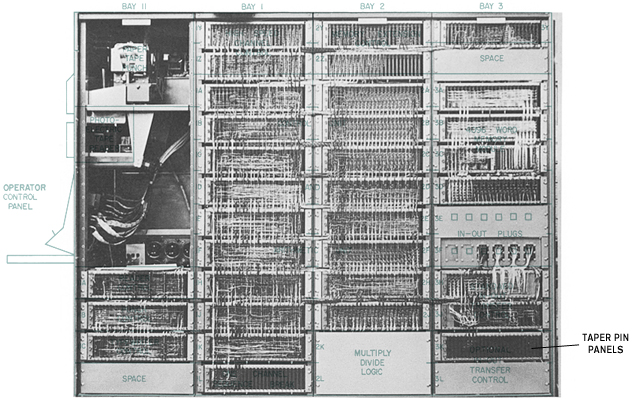
The taper pin panels of the PDP-1, located near the bottom of bay 3.
Image: Composite of images by DEC, PDP-1 Maintenance Manual F-17, 1962.
This is, how the control boxes were connected in the standard setup:
usage:            -PLAYER 1-                                -PLAYER 2-

bits/pins:        0  1  2' 3  4  5' 6  7  8' 9 10 11'12 13 14'15 16 17
                  |  |  |  |                                |  |  |  |
device:           CTRL BOX A                                CTRL BOX B
                  |  |  |  |                                |  |  |  |
wiring:           L  R  T  F                                L  R  T  F
                  |  |                                      |  |
               HYPERSPACE                                HYPERSPACE
(Bit-order as transferred to the IO register by the "iot 11" instruction.)
And here is the circuit diagram for the original control boxes:

Circuit diagram of the original control boxes. The diagram came along with some listings from the archives of J.M. Graetz, donated to the iMusée, the Musée de l'informatique du Quebec, by Brian Silverman.
The schematics at the bottom show the setup of the iot 11 instruction. "PA" is a pulse amplifier, the I-O mixer interfaces with the IO register. (IO must be cleared before reading the input.)
Clockwise (right) and counterclockwise (left) turn were operated by a common lever, and thrust/acceleration and hyperspace by a second one (triggering a jump by pushing the lever forward, away from the player), while torpedoes were fired using a separate push button. — Please mind that Steve Russell also remembers in his oral history interview some early control boxes using buttons instead of levers (see below).
┌─────────────────────────────────────────┐
│                                         │
│                                         │
│                                         │
│     ┌──LEVER──┐                         │
│     │         │                         │
│  [LEFT]····[RIGHT]    [HYPERSPACE]──┐   │
│                            ·        L   │
│                            ·        E   │
│                            ·        V   │
│                            ·        E   │
│                            ·        R   │
│                         [THRUST]────┘   │
│        [FIRE]                           │
│          │                              │
│        BUTTON                           │
│                                         │
│                                         │
└─────────────────────────────────────────┘
Layout of the control elements on the control boxes (schematic, top view).
Hyperspace was triggered in Spacewar! 2b by letting go of the lever (as defined by the program), all later versions of the program triggered a jump on the deployment of the signal.
According to Thomas A. Tilley, who engaged in recreating the original control boxes in his Game Controller Hacking class at Payap University featuring a talk by Dan Edwards on the subject, this was the kind of lever switch used:
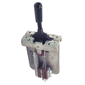
Kind of lever switch used for the original control boxes.
Image: surplussales.com.
The fire button triggering the torpedoes was a simple and inexpensive small red push button, the case was made of wood with a sloping Bakelite top (as recalled by Dan Edwards). And, in case you haven't seen this image before, here is what the control boxes looked like, according to J.M. Greatz ("The Origin of Spacewar", Creative Computing, Aug 1981; p.62) and confirmed by Dan Edwards to be "a fair artist's rendition of [the] controller we commonly used":
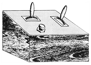
Drawing of a Spacewar! control box (MIT, 1962) as recalled by J.M. Graetz.
Image: J.M. Graetz, "The Origin of Spacewar", 1981.
And here is what the control boxes looked like in action:
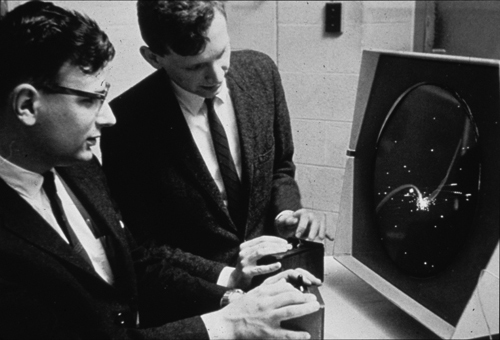
The original Spacewar! control boxes in action.
Dan Edwards (left) and Peter Samson (right) playing Spacewar!, 1962 ca.
Photo: DEC, via the Computer History Museum (accession 102631264).
We may suppose them to have been of a stable build — and also of some weight —, resisting pushes and other movements induced by heavy gaming. On the other hand some importance was put in the silent (read, stealthy) operation of the levers and switches. Moreover, we may infer from the image above that the levers were operating fairly smoothly as indicated by the lightweighted hand postures of the players.
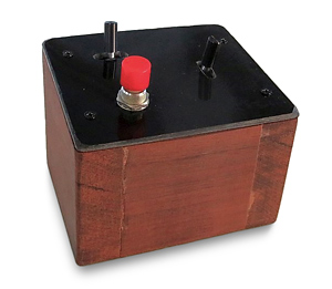
Reconstruction of an original control box by Thomas A. Tilley.
Image: Thomas A. Tilley, 2015 (edited)
The Very First Control Boxes
In history, there's always a first before the first, and there's no exception to this in computer history. As the living proof of this, here is a sketch of the very first control boxes featuring push buttons only as recalled by Steve Russell in 2003:
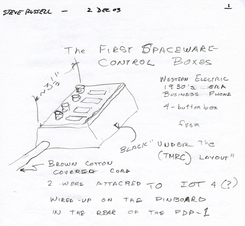
Sketch of the very first Spacewar- control boxes using pushbuttons as recalled by Steve Russell in 2003.
Source: pdp-1.org / The CHM PDP-1 Restoration Team.
The version that I remember quite clearly, and nobody else does, so I think they must have died very early — there was a 1930s design, 4-pushbutton block that was used for buzzing buzzers in an office; so you'd have a receptionist who had maybe one or two or three lines on a phone and when one of them rang, she'd pick it up, find out who it was and then buzz the buzzer to get that person to pick up the phone. Those were nice because you could hold them in one hand and play them like a flute. But they died very quickly; they were designed for being pushed a few times a day, and it turned out that there was a fatigue problem when they were pushed hundreds of times a day. And so they died fairly early.
(Oral History of Steve Russell, interviewed by Al Kossow, rec. 9 Aug 2008, CHM catalog no. 102746453, p.16)
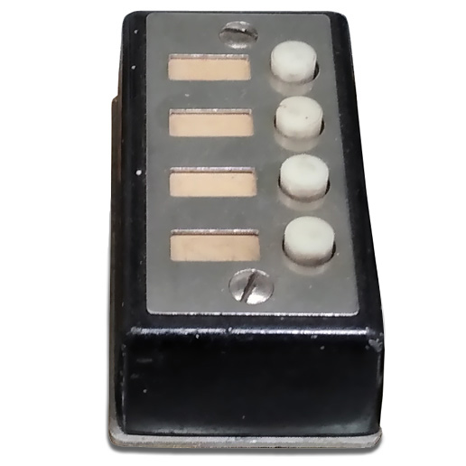
A similar block of telephone switches (as confirmed by Steve Russell).
From the collection of the American Museum of Telephony / JKL Museum of Telephony,
photo by Joseph Fredrick, 2023 (cropped and edited; N.L.).
As annotated in the sketch, these very first control boxes were about 3.5 inches wide and featured four 1930's business phone style pushbuttons mounted on top of a black housing. (We may assume that the top plate was made of Bakelite, quite like it has been reported for the "original control boxes".) Further, the boxes were connected to the taper pin block of the PDP-1 by a brown cotton covered cord (quite 1930's style, too) and were (presumably) read using the instruction "iot 4" rather than the instruction "iot 11" that we've learned to recognize and love in the surving source codes of Spacewar!.
The (To Date) Last Original Control Boxes
And, as a final rounding off of the topic, here are the schematics of the to date last incarnation of the control boxes used for the public display at the Computer History Museum, as sketched in 2005 on the white board of the PDP-1 Restoration Team:
Early sketch of the control boxes and wiring schematics used at the CHM (2005).
Source: pdp-1.org / The CHM PDP-1 Restoration Team.
Notably, this wasn't the final design which features the hyperspace button in the middle and Thrust and Fire to the right of it, modeled — as a final twist in history — after the controls of the arcade game Space Duel. (Source: Ken Sumrall.)
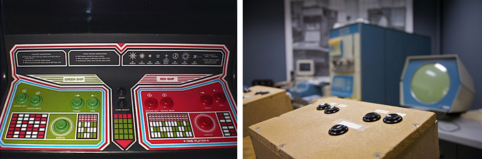
The controls of Space Duel (left) and the control boxes at the CHM (right).
Images: basementarcade.com (Space Duel panel) and Marcin Wichary, 2008, Creative Commons.
Final layout of the control boxes at the Computer History Museum (CHM).
Image: N. Landsteiner, 2015
That's all for now, next time we'll investigate the gravity code skipped here.
Vienna, July 2014
www.masswerk.at
In case you would have found any errors or inconsistencies, or would have additional information,
please contact me.
*****
◀ Previous: Part 4: The Outline Compiler
▶ Next: Part 6: Fatal Attraction — Gravity
▲ Back to the index.