Episode 1: Preliminary Considerations
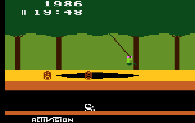
Before we begin to specify our game, we may want to have a closer look at the platform we are targeting, what it can do and what it can't. The Atari VCS is capable of some impressing feats, like producing a palette of 128 colors, when 8 of them where considered a luxury on expensive systems, or running a 6502-family microprocessor at about 1.2 MHz, when 1 MHz was the top of the range for “serious” computers, but it's also an example of severe limitations. The whole point of having platform studies may be for the sake of better understanding Atari VCS games. So we may want to include these specifica into our considerations, right from the beginning, much like Pitfall, probably the most famous game on the Atari 2600, has been famously sketched out on a sheet of paper, condsidering, what can be done on the system. However, Pitfall still took one and a half years to complete, so we may want to pick something less fancy for a game which we expect to be done in a month.
The Atari Video Computer System (VCS)
We had already a cursory look at the Atari VCS last year, when we investigated the workings of pure-TTL, signal generator type arcade video games and Computer Space in particular. I highly recommend to have a look at this for some background on how video signals are generated and how first generation arcade video related to the VCS. Because, generating games like Pong and Tank is what the Atari VCS is all about, anything exceeding these capabilities was considered a bonus. However, we're having a closer look at the VCS here again, but this time in exclusiveness.
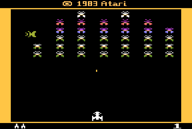
September 11, 1977 saw the realease of the Atari Video Computer System™, better known by the acronym VCS, later renamed Atari 2600 (following to the introduction of the Atari 5200 in late 1982). Developed under the code name “Stella” by Atari's external R&D division Cyan Engineering in the Northern California Sierra Nevada foothills, Grass Valley, the VCS was Atari's master plan to make video games a common home appliance. In fact, Atari gambled its very existence on the success of the system with Nolan Bushnell having to sell Atari out to Warner Communications in order to finance the project. As we'll see, the system was all about cost reduction, in order to undercut the competition in price, namely Fairchild's Video Entertainment System™ (or VES, renamed Channel F in a reaction to Atari's quite similarly named product), a cartridge based video game system released in 1976. However, the VCS wasn't a roaring success right from the beginning: 250.000 units sold at a price of just below $200 in 1977 and only 550.000 of a production run of 800.000 were sold in 1978, as the video arcade industry had lost some of its novelty. The following year, 1979, brought a turn around by the even more cost reduced Model A, now produced in Hong Kong, and Taito's Space Invaders, which revitalized the languishing arcade industry. The VCS became the favorite Christmas gift of the year with sales accounting to a million units and, when Space Invaders became a licensed title on the VCS early next year, sales doubled to even 2 millions. (We may note that this sucess came not without irony, since a game like Space Invaders is already out of the specs of the VCS, which was beginning to show its age, right at its heyday.)
The rest is history, with a slice of wood grain: By 1982 the Atari VCS/2600 had sold about 10 million units, before the industry plunged into the Great North American Video Game Crisis (AKA Video Game Crash).
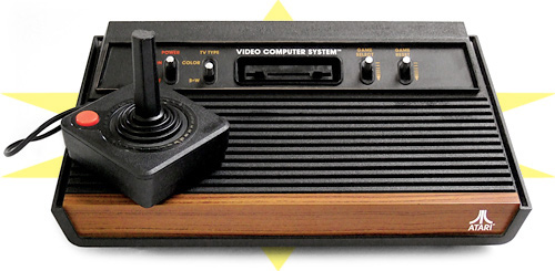
The Atari Video Computer System™ or short VCS, also known as the Atari 2600.
Here the four-switch "wood veneer" version as produced between 1980 and 1982.
(Image: joho345 / Wikimedia, public domain; edited N.L.)
As mentioned above, the VCS was all about generating first generation video games, like Pong, Tank, or Gotcha.* Simple two-player games, where two human opponents could encounter each other in and through the virtual realms of a raster-scan CRT screen, without any physical contact, in a refined match previously available only to accomplished players of racket sports, but now brought to the masses in a pure environment, where players could match regardless of age, state of intoxination, or bodily fitness. (We may contemplate the cultural relapse into physical barbarism which had been introduced by later fighting games and “beat'm'ups.”) Typically, there were two simple representations of the players, a single ball, or a single projectile for each of the two players, and a simple, mostly symmetrical background to represent the playfield. The VCS had all on board required to generate a game of this kind, as in the so-called player-missile graphics.
*) Note: While admittedly not one of the best games ever, Gotcha may be one of the most underrated games in gaming history, since it was the first game to be staged in an all-virtual environment, without any similarities to real-life objects. However, it wasn't much of a success, as the general public seemed to prefer games which could be related to in terms of real world knowledge. As a consequence, there was never an official release of Gotcha for the VCS and the arcade game is best remembered for its unique, breast-like controllers (as in “the boob game”).
Hardware
The Atari VCS / 2600 is rather simplistic in terms of hardware: It consists of merely 3 integrated chips, namely the Television Interface Adapter (TIA) for producing video and sound signals, a MOS Technology 6507 MPU, and a 6532 PIA (in Atari terms the RAM-I/O-Timer chip or short RIOT). Also, there are 7 user operable switches and 2 control ports, but only the power switch and the TV channel selector are defined by hardware, leaving the rest to the software to cope with (hence, the naming of these switches is rather convention than anything else.) The output signal produced by the TIA is composite video and two channels of mono sound, transformed by an RF modulator ready to be plugged into a TV set.
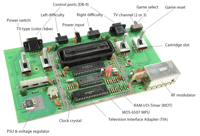
Atari VCS / 2600 hardware (four-switcher).
Image: iFixit — Atari 2600 Teardown (annotations by me, N.L.)
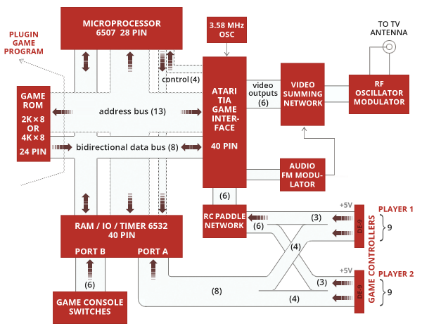
Atari VCS / 2600 block diagram.
(Numbers in parentheses give bus widths in bits.)
Image: N.L. after the TIA-1A Manual (Jay Miner, 1976)
and the “Reconstructed” Stella Programmer's Guide.
The Television Interface Adaptor (TIA)
The Television Interface Adaptor, commonly known by its acronym TIA, is the heart of the VCS: A custom designed chip incorporating all the principal workings of an early video game in an integrated 40-pin DIP package. But it comes with an handicapt, as there's no notion of a 2-dimensional screen image. That's right, the TIA is a serial offender, just repeatedly clocking out a scan line according to the settings in its registers. Anything related to the vertical dimension of the picture has to be controlled and set up properly in time by software. As for the hardware, there's only a single dimension, namely time, translating to intensifications of pixels as the video signal progresses along the scan line.
The TIA is clocked at 3.58MHz, thus dividing a TV scan line into 228 clock counts. A scan line starts with 68 clock counts of the horizontal blank interval (HBLANK), leaving 160 clock counts or visible pixels for the rest of the line, which is then terminated by the horizontal sync signal (HSYNC), which starts the next phase of HBLANK. This is also all what the TIA is arranging for. In order to populate the visible portion of a scan line, there are a few entities, which make up the player-missile graphics:
- Two players (a strip of 8 pixels each).
Each player has a single color register assigned to it.
Also player sprites may be streched to 2× or 4× the normal size and may be replicated to up to 3 copies at varying distances. This is controlled by a single register, allowing just a restricted set out of all possible variations as in:- single copy, normal / double / quadruple size
- 2 copies close / medium / wide (at 16 / 32 / 64 px distance)
- 3 copies close / medium
- Two missiles (a single dot each).
Each of the two missiles takes the color of one of the player sprites. Missiles may be streched to 1×, 2× 4×, and 8× the normal size. Unlike the player sprites, missiles may not be replicated. - A ball (a dot).
Like the missiles, the ball may be streched up 8× the normal size. It has no color of its own, but takes the color of the playfield. - The playfield (20 bits, replicated to 40 wide pixels at 4 clocks).
2 and a half 8-bit registers define the pattern of the playfield (background graphics), filling half a screen with pixels streching over four color clock cycles. The other half is complemented either by a repetition of this pattern or by its mirror image.
The playfield has its own color register, rendering the entire playfield graphics in the same color. This color is also assigned to the ball. - The background color.
(Object priorities are as follows: player 0 & missile 0, player 1 & missile 1, ball & playfield, background. The stacking order may be changed by a special control bit, putting ball and playfield before the other objects.)
In order to compose these entities into a single line, there are several counters implemented in the TIA, accounting for the position, the strech or replication (by delays) of the various objects. However, the TIA doesn't implement this by normal, digital counters as may be expected, but by more cost effective polynomial counters. These are guaranteed to produce a unique, repeating sequence, but the iterative values are out of sequence. Thus, we can't simply instruct the TIA to display an object A at position X. Rather, we have to reset the appropriate counter by writing to a strobe register, just at the right clock cycle, as the electron beam is swiping ower the particular position in the scan line. — But more on this later.
While all this is controlled by writing to registers, there are also registers for read access, namely collision registers, reporting any overlap of the major objects (15 collision states in total). Moreover, the TIA is also responsible for sound (rather crude sound that is) and providing paddle input data, but we'll cover this later, when we'll need any of this.
The MOS 6507 MPU
The 6507 is your customary 6502 processor, but it has only 13 of the normal 16 address lines connected and no interrupt pins in order to fit into a more cost effective 28-pin DIP package. Otherwise, it's the the same as the 6502, but it can only “see” 8K of address space. (Since the missing pins are those for the most significant address lines, this 8K space is mirrored 8 times over the internal 64K / 16-bit address space.) In programing term, it's common to refer to the 6507 as 6502, because it's essentially the same chip, especially for the instruction set (including the “illegal” opcodes.)
The 6507 is clocked by the TIA at a third of its own clock rate, providing a clock pulse on every third of its own. This results in a clock rate of 1.19MHz for the 6507, which is pretty high as compared to most home computers of the time. However, the electron beam of the CRT progresses over three pixels for every clock cycle of the 6507 — and the minimal cycle count for a simple NOP is two cycles. For a simple store instruction, like "STA $00", 9 pixels are passing under the beam!
The basic means of synchronizing the 6507 with the TIA is by strobing (meaning, writing any value to) the WSYNC (wait for sync) register of the TIA, by this instructing it to supply no further clock pulses to the 6507 until the next scan line is reached. Thus, the 6507 is effectively put to sleep, without any notion of what's going on around it, to be raised again at the start of the next phase of HBLANK.
The RAM-I/O-Timer (RIOT)
A 6532 PIA provides not only timers and ports for reading various console switches and the state of the two joysticks, but also provides a whopping 128 bytes of memory (0.125 K). However, so we're not going to crace out over this lush supply of resources, this is also to be used for the CPU stack of the 6507, growing down from the top of the RAM.
(For the purpose of the stack, the address range $0000-$00FF, which includes the primary image of the RIOT, is also mapped to $0100-$01FF, where RAM is expected by the CPU.)
Address Space
To complete the image, we're just lacking the ROM cartridges, which came in two sizes, 2K and 4K, and map to the top 4K of the 8K address space. (In the later times of the Atari 2600, special cartridges included even larger ROMs, implemented by bank switching operated by read access on special address latches.)
The entire address map of the VCS, as seen from the 6507, looks like this:
$0000 - $007F	128 bytes    TIA registers
$0080 - $00FF	128 bytes    RAM / CPU stack
$0200 - $02FF	256 bytes    RIOT registers
$1000 - $1FFF	4k           ROM

$0100-$01FF map to $0000-$00FF.
Or, if curious what's “living” in the “holes”, here in more detail:
$0000 - $002F                      TIA Primary Image
$0030 - $005F       [shadow]       TIA
$0060 - $007F   [shadow-partial]   TIA
$0080 - $00FF                      RAM Primary Image (zero page image)
$0100 - $002F       [shadow]       TIA
$0130 - $005F       [shadow]       TIA
$0160 - $017F   [shadow-partial]   TIA
$0180 - $01FF       [shadow]       RAM (CPU stack image)
$0200 - $022F       [shadow]       TIA
$0230 - $025F       [shadow]       TIA
$0260 - $027F   [shadow-partial]   TIA
$0280 - $029F                      RIOT registers Primary image
$02A0 - $02BF       [shadow]       RIOT registers
$02C0 - $02DF       [shadow]       RIOT registers
$02D0 - $02FF       [shadow]       RIOT registers
$0300 - $032F       [shadow]       TIA
$0330 - $035F       [shadow]       TIA
$0360 - $037F   [shadow-partial]   TIA
$0380 - $039F       [shadow]       RIOT registers
$03A0 - $03BF       [shadow]       RIOT registers
$03C0 - $03DF       [shadow]       RIOT registers
$03E0 - $03FF       [shadow]       RIOT registers

$0400 - $07FF   Mirror of $0000 - $03FF
$0800 - $0BFF   Mirror of $0000 - $03FF
$0C00 - $0FFF   Mirror of $0000 - $03FF

$1000 - $17FF   Lower 2K Cartridge ROM (4K cartridge)
$1800 - $1FFF   Upper 2K Cartridge ROM (2K cartridge)

-------

$2000 - $3FFF   Mirror of $0000 - $1FFF
$4000 - $5FFF   Mirror of $0000 - $1FFF
$6000 - $7FFF   Mirror of $0000 - $1FFF
$8000 - $9FFF   Mirror of $0000 - $1FFF
$A000 - $BFFF   Mirror of $0000 - $1FFF
$C000 - $DFFF   Mirror of $0000 - $1FFF
$E000 - $FFFF   Mirror of $0000 - $1FFF
It's common usuage to use the highest mirror image for a program to go in ROM (start address $F000) and to use the lowest image for the system addresses. The common programmer's weapon of choice in the Atari homebrew communities is the DASM cross-assembler, comming for all sorts of systems and with header files for the various system addresses of the Atari VCS / 2600. In order to blend in, we'll use this as well.
The go-to source for detailed information on the TIA and RIOT registers is the “Stella Programmer's Guide” by Steve Wright (1979, updated by Darryl May in 1988), availble as scans from the original (PDF), as a “reconstructed,” newly type-set version (PDF) and in HTML.
Composing TV Images
By this, we should have all the provisions required for composing a 2-dimensional TV image. Here, we'll go for NTSC, non-interlaced (we can't do interlaced), 60 frames per second, and provide the data for PAL later.
In NTSC, a field or non-interlaced frame consists of 262 horizontal lines.
These are made up by:
- 3 vertical sync lines (VSYNC), allowing the cathode beam to position itself at the upper left corner of a screen,
- 37 lines of vertical vertical blank, followed by
- 192 “safe” lines of TV image (known as the kernel), and
- ending in another 30 lines of overscan (which may or may not be partially shown by a particular TV set).
Combining this with what we already know about the horizontal composition of a line (68 TIA cycles of HBLANK and 160 cycles of visible image, followed by HSYNC), we arrive at the following picture (or, rather, diagram):
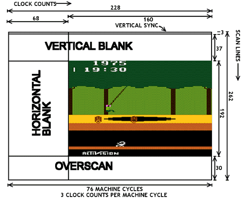
Atari VCS playfield timing, TIA clock counts and 6507 cycles (at the bottom).
(Image: AtariAge, based on the "Stella Guide" VCS developer documentation.)
Here is the relevant data for implementing both NTSC and PAL (notably, the horizontal timing is the same):
| NTSC | PAL | |||
|---|---|---|---|---|
| scanlines | microseconds | scanlines | microseconds | |
| VBLANK (including 3 VSYNCs) | 40 | 2.548 | 48 | 3.085 |
| KERNEL | 192 | 12.228 | 228 | 14.656 |
| OVERSCAN | 30 | 1.910 | 36 | 2.314 |
| FRAME | 262 | 16.686 | 312 | 20.055 |