Episode 2: (Re)cherchez la Machine
Where we risk a glance at the machine in particular and investigate the workings of early video games in general. Eventually, we even encounter the Spanish Inquisition. Be prepared and expect the unexpected.
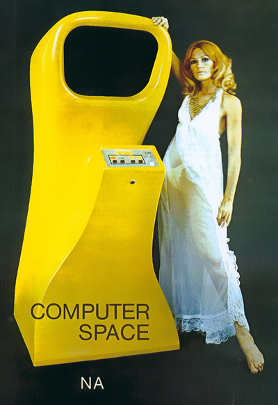
The famous original Computer Space flyer art by Nutting Associates, Inc.
No, the machine is not as big, this is either a photo montage or a flagrant case of
— ahem — "dwarf-shaming". OK, let's shit-storm. Does NA have a Twitter handle? ;-)
(No, don't do it, stop it! Immediately! They are out of business anyway,
for more than 40 years by now.)
If you know me and my write-ups, you know that I can't do without devoting at least one episode to research on the subject. So this is the episode. (Buckle your seat belts.) This time we won't talk much about the PET as a platform, because this is all well known, but about the game/machine we're trying to recreate in software by the PET's technical means. We investigated Computer Space for RC2016/10 already, when we wrote a simulator for the DEC PDP-1, but not everyone may be familar with this. Also, I've learned a bit more about this amazing contraption in the meantime. Last, but not least, we may want to know what we're trying to copy achieve…
Let's Talk About Computer Space (1971)
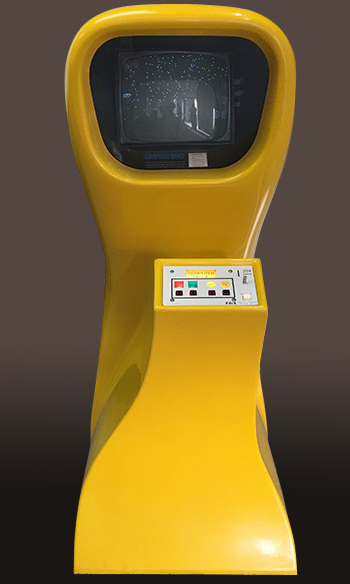
The actual Computer Space in its glorious, Space-Age-y cabinet.
The fiber glass cabinet came in colors yellow, red and blue
(the later 2-player version came in green — and then there was
at least one white prototype machine as seen in "Soilent Green").
Photo (edited; N.L.): Tekla Perry, via IEEE Spectrum.
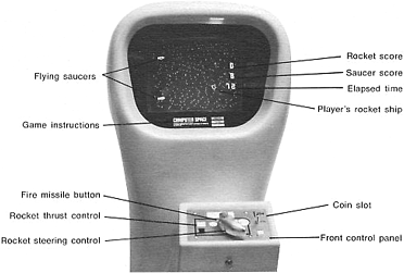
1) Gameplay and Player's Experience
For a beginning, let's have a look at the machine's gameplay and features, apart from its sculptured fiber glass cabinet (designed by Nolan Bushnell), so-to-say, the game's ingredients:
- One rocket ship, representing the player. There are 32 rotational positions, none of which is perfectly vertical or horizontal, providing a characteristic drifting impression of the spaceship while moving. Like in Spacewar!, thrusting adds to the rocket's current motion vector. (There's also a thrusting animation, consisting of two alternating dots.)
- Two saucers, aligned vertically and separated by a constant distance, half an NTSC frame apart from each other. Saucers move at constant speed stricktly in one of 8 directional angles (up, down, left, right, and diagonally, with the saucers moving faster along diagonals) and stop at a dime. Also, a saucer's missile direction is limited to these 8 angles.
- There's a notable amount of off-screen area, both vertically and horizontally, roughly equalling the V-BLANK and H-BLANK off-screen regions of the NTSC TV signal. (BTW, the visible portion shares a 4:3 aspect ration with the normal, analog standard TV.)
- Two missiles in total, one for the rocket ship, one of the saucers. Only one of the saucers is actually shooting, conveying the very nature of the second one as a mere mirror image. So there is actually just a single saucer, appearing twice at a vertical offset.
- The rocket ship's torpedoes are fired from the very center of the ship, while the saucer's missile always appears at the lower right side of the saucer's central "rim", regardless of the direction of the shot.
- There's a spinning animation for the rocket ship, when hit.
- When one of the saucers is hit, the screen blinks (once) in reverse video. The screen blinks also on the occasion of the rocket being hit.
- Scores are displayed at the right side of the screen as a single digit 7-segment-style numeral. While intended to be in decimal, there's a common issue, typically with the player's score, wrapping around at 16 (instead of 10), thus displaying hexadecimal "garbage" for scores in the range of 10 to 15. (The enigmatic display graphics are the actual output of the Intel 7448 BCD-to-seven-segment decoder chip used by the game.)
- Below of the two scores for rocket and saucers, there's a two digits time display, counting up from zero to 99. When the counter resets, the game either ends, or, if the player managed to outscore the saucers (based on the single digit scores, ignoring any overflow), the player qualifies for another round of overtime play. This extended play, tagged hyperspace, is displayed in reverse video (black on white), conveying "a vision of daylight in outer space."
Otherwise, the rocket ship vanishes at the instant, the saucers are reset and the game goes into attract mode (see below). - There's a lush amount of background stars, providing both visual context for the game's outer space theme and an aid for positioning and judging movement.
- There's a "rotating" animation, consisting of 3 streched dots, at the center of each saucer's "rim." Not to much of a surprise, the animation is synchronized for both of the saucers (as they are, in actuallity, just a single one). The animation is performed in both directions (left and right), at at least two speeds (and none, for a resting saucer), kept constant for any of the legs of the saucer's trajectories (as saucers move randomly for some time in any of their 8 directional angles).
- There's also another animation-like feature, consisting of two half-sized blinking pixels, appearing to the upper left and upper right side of a saucer, respectively. As these blinking pixels are apparently synchronized with the rotation of the central rim-animation and this behavior isn't exhibited by all of the cabinets, this may be rather due to a timing issue (probably in analog circuitry) than being an intended feature. (Just my own theory on this.)
- The game features an attract mode, while running idle, consisting of the sole saucers roaming the screen, with scores displayed as at the end of the previous game and the time counter reset to "00". With the beginning of a game, the rocket ship enters the screen (apparently always engaged in a slightly diagonally downwards motion already).
Otherwise, there is no dedicated attract screen or any title graphics. - Saucer positions are reset to random offsets, when they are hit. In contrast, the player's rocket reappears in the same spot and state as before, but motionless, when destroyed. This may result in the saucers merclessly pounding the player's ship like a "sitting duck," as long as they are remaining at the same shooting angle.
- Overall, the saucers' aiming AI (including motion look-ahead) is surprisingly good and makes them a pretty hard oponent — which does make sense, considering that this is a time based game with extended overtime play as the incentive, just like most of the prevalent elctro-mechanical arcade games of its time. (We may add disbelieve and frustration as another incentive and general motivation for a player's/customer's engagement with the game.)
- There is a number of amazing, analog sound effects adding to a sonorous background hum: A bleeping turn signal, a rather subtle, exhaling thrust effect, two dedicated, distinctively screeching sounds constantly on while any of the missiles is active, and a rich explosion effect. (The overall effect of this sound-scape is, in its richness, more Pac-Man than Asteroids.) — Defenitely a feature, we won't be able to recreate on the PET.
While this may seem like a rather long list, the game is in verity a study in the least viable product: There's virtually none which isn't an absolute requirement for a working game, and the features present are also stripped to the bare minimum, with a notable mention to the two saucers being in actuallity just a single one, appearing twice at a vertical offset by half a frame.
There are actually just two features in the entire list that may be considered as somewhat luxurious:
- A lush amount of background stars. (Comes for free.) — Never again has outer space been so dense.
- The central rim animation of the saucers. (Considerable effort involved.)
Whoever signed responsible for this latter feature (be it Nolan Bushnell or Ted Dabney) showed a significant amount of insight into video game aesthetics, when there was principly just a single one in existence, namely Spacewar!: Like the pulsing and spinning animation of the central, gravitational star in Spacewar!, the saucers' rim-animation is the very embodiment of the presence and agency of the machine, thus lending the game its soul. — There couldn't have been found any other feature more worthy of any extra investments, as this is really the one essentially adding the "Computer" to "Computer Space," in terms of the player's experience!
Remember, when computers were, at least in the imaginary of the public, all about blinken lights? Of course, there had to be some in a game named "Computer Space," and this was the perfect place to incorporate them.
*
When the game was eventually described for its product flyer, it's rather cute to see, how the description is maneuvering around the two principle shortcomings of the game: The lack of gravity, crucial to any Spacewar!-like game, here actively advertised as "gravity-free outer space," and the careful choice of plural and singular forms, when it comes to the saucers, using singular, where ever a saucer is mentioned as an active agent, like when firing missiles, and plural form, when they serve as merely passive objects, like of the player's endeavors to hit them.
(Apparently, someone had consulted a lawyer.)
And this is how Nutting Associates advertised the game in the flyer, the cover art of which you have seen above already:
HOW COMPUTER SPACE WORKS AND PRODUCES
BEAUTIFUL SPACE-AGE CABINET attracts players of all age groups. The player is additionally attracted by two flying saucers moving about in formation on the playfield while the unit is in its non-activated state.
EXCITING PLAYER ACTION occurs as coin is inserted and start button is pushed to activate the unit. A rocket ship appears out of nowhere and at the same instant the once friendly saucer begins firing missiles at the rocket ship. Now at the controls of the rocket ship, you begin to evade the missiles bearing down on you and maneuver into position to fire your own missiles at the saucers. The thrust motors from your rocket ship, the rocket turning signals, the firing of your missiles and explosions fill the air with the sounds of combat as you battle against the saucers for the highest score. Outscore or hit the saucers with your missiles more times than they hit you for extended play in hyperspace. Attain hyperspace and the playfield turns white and gives you a vision of daylight in outer space. Thrill to reality of controlling your own rocket ship in gravity-free outer space. Battle the saucers in a duel of wit and coordination!
CHECK THESE UNIQUE FEATURES
- Coin acceptor, rocket thrust button and rocket steering controls are the only moving parts in the entire unit. No mechanical relays, films or belts.
- Adjustable play time from 1 minute to 2½ minutes.
- Standard unit 25¢ play convertible to 2/25¢ by the throw of a switch.
- Tamper-proof coin meter.
- Continuous blinking panel lights and back-lit playfield for player attraction.
- Integrated circuits in low-current solid-state construction insure the ultimate in long life.
- No repeating sequence; each game is different for longer location life.
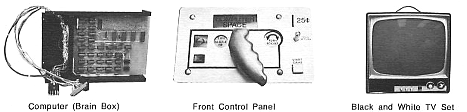
COMPONENTS? THERE ARE ONLY THREE ASSEMBLIES IN THE ENTIRE UNIT
COMPUTER (BRAIN BOX) is sealed and carries a full one-year unconditional gaurantee if not tempered with. FRONT CONTROL PANEL houses the only moving parts in the unit—the rocket ship controls and coin acceptor. BLACK AND WHITE TV SET has the life of any new black and white reciever—no modifications have been made to affect its reliability.
Wheight 98 lbs; Dimensions 30" wide × 67" high × 30" deep.
Nutting Associates, Inc.
500 LOUNGE AVE., MOUNTAIN VIEW, CA
Mind the joystick type controller originally intended for the game (it didn't prove durable enough for heavy duty on location.) The flyer illustrates pretty well, how bringing a game to the audiences was about selling it to the operators in the first place, and it does so (among others) by comparing to the prevalent electro-mechanical arade games and their multiple points of failure. — Homework: Imagine a flyer trying to convince operators of "Flappy Bird," «Player taps screen repeatedly to level flight of bird on black and white TV set as merry bell tones are filling the room…» (Yay, that'll work, probably.)
Storywise, there isn't much going on in this description. Unlike with later video games, it is not adding to the backstory, it doesn't provide any specifics about the plot, like defending a moon base, nor does it pick a favorite constellation or star, like Atair, as the location. We don't know about the action, but that there is action. We don't know, where we come from nor where the saucers came from, nor do we know about their cause and why they are attacking, or why we brought a photon torpedo launcher in the first place. But we may note that it subtly includes the attract mode into the "story", by "the once friendly saucer begins firing missiles." (So we are expected to be caught by surprise, like in, "insert coin for ambush." Pretty much Perl Harbor in outer space.) But this doesn't provide much in terms of a long-term story telling extended narrative universe — so this isn't stuff for the next movie franchise (like the one long-running outer space live-action movie series of a rather dark, non-existing comic novel, which may have been called Light Sabres, being about an ambivalent super hero in a black knight's costume and his origins). Sorry. — But it's interesting that there is even this tiny bit of a story, and, really, this is certainly enough of a story for any arcade action video game.
In case you're still with me, you may want to enjoy a tour of the machine (here a red specimen) and its gameplay:
Computer Space review video, gameplay at 23:00 (youtube.com)
2) Technical Basics
Notably, despite of its name, Computer Space was not a computer as defined by the presence or absence of a Central Processing Unit (CPU). Rather, it was, as Nolan Bushnell once put it, a "big, fancy signal generator," implemented in digital, solid-state Transistor-to-Transistor Logic (TTL) as in (mostly) 74xx-series integrated logic chips.
You may have heard or read that Computer Space achieved its revolutionary goals by somehow manipulating the timing of the repetitive signal of the video beam to the effect of spacial displacements of its on-screen objects. But, how and by what kind of breakthrough technology could it master its objectives, thus bending the very space-time-continuum? — Let's see.
*
But first, I've to confess that I'm drawing my entire wisdom on the subject from a single source, namely "The Textbook of Video Game Logic; Volume 1" by Arkush, William (Kush N' Stuff Amusement Electronics, Inc., Campbell, CA, 1976). This book was meant as an introduction to the workings and to the maintenance of first generation arcade video games, addressing operators either new to the business or switching to this kind of arcade games, when the technology pioneered by Computer Space had become the prevalent one and CPU-based video games were just at the horizon. The book is available for download here (PDF). This is also the place to thoroughly thank Ed Fries for pointing this out in his writeup on Fixing Color Gotcha (May 2016), where he's eventually identifying this rare version of an Atari game as the very first color game, we have any notice of. Also, it's thanks to Ed Fries' thorough writeup on his endeavors of Fixing Computer Space (March 2015) that made me interested in the game in the first place. If you aren't familiar with Ed Fries' writeups, go there now and read them.
*
So here is
A Brief Introduction to Bending the Space-Time-Continuum For the Sake of Video Games,
or How to Construct an Optical Warp Drive (AKA Signal Generator) from Simple Binary Logic
Since this is all about generating video images, let's dive, for a start, into the intrinsics of analog video signals, as defined by the NTSC standard: First of all, the image seen on the Cathode Ray Tube (CRT) is produced by a raster scan process, meaning, the image is transmitted and displayed in horizontal lines, beginning at the left and progressing to the right, from the top of the screen down to the bottom, line-by-line. The CRT does so, by swerving its cathod ray beam at constant speed in a scanning motion across the screen, thus activating the phosphor coating at the front glass in order to produce the image by variations of brightness. Any variations of intensity (brightness) as displayed on the screen are proportional to variations in intensity in the signal. (This really is what an analog signal is all about.)
TV Images
The NTSC standard defines a signal for an animated raster scan image produced by 525 lines at 60 frames a second (for PAL, its 625 lines at 50 Hz). — That is, it's in actuality 59,94 Hz since the color signal was introduced, but TV sets are somewhat robust and we will ignore color here completely and deal with strict black and white only. — Moreover, the response of the analog elements as well as the bandwith of the carrier signal are somewhat limited, so a frame is usually transmitted in two alternating fields of just 262.5 lines, where each odd field is displayed at an offset of half a line (so it's 263 lines for an even field and 262 lines for an odd field), thus transmitting 30 interlaced image frames a second. In order to allow the TV set to drop its beam to this half-line offset at the first line, odd fields start with an offset of half an horitzontal line. Since it's also this offset that causes the TV to drop its beam to display an odd field, we may also send a non-interlaced signal consisting only of even fields of 262 lines at 60 Hz. And this is also what we're going to discuss here: Non-interlaced black and white composite video.
In order to produce the raster image, the TV traces its electron beam across the screen in a motion produced by a sawtooth waveform, displaying each line at slightly slanted angles and retracing to the left, whenever it reaches the end of a line (right image border). Just the same, the TV has to retrace its beam to the upper left corner as it reaches the end of a field, requiring a somewhat longer vertical retrace. At both the horizontal and vertical retraces the beam is shut off (blanked) corresponding to horizontal blank (H BLANK) and vertical blank (V BLANK). It's also these blankings that are used to synchronize the TV set with the incoming signal. Horizontal and vertical sync signals (combined COMP SYNC) combined with the actual video stream is what is known as a composite video signal.
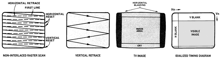
Production of a non-interlaced TV image (based on The Textbook of Video Game Logic, Vol. 1)
The vertical retrace (V BLANK) starts with 3 horizontal sync pulses and lasts for 40 lines in total, reducing the visible area of the image by the same amount of lines. Also, there is an amount of lines at the very bottom of an image (or field) that a TV set may or may not be able to display, known as overscan (which is generally not considered a "safe" image area). Just the same, the visible image is also reduced at its horizontal extent by the horizontal retrace (H BLANK).
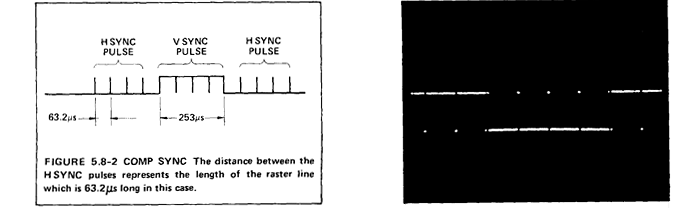
Horizontal and vertical sync pulses as in the COMP SYNC signal.
Timing diagram (left) and as seen on an oscilloscope (right).
(The Textbook of Video Game Logic, Vol. 1; p 60)
Video Images in TTL
So, what does it take to produce a composite video signal by binary circuits? Just a clock and a couple of 4-bit counter chips (as there are plenty in the 74xx series), known as sync chain. On each clock pulse, we'll trigger the input of the first counter chip, and each time this overflows and resets, it will clock the higher order one in turn. By this, we're dividing a horizontal line in a series of pixels (or, rather, we really should speak of pels here, as in Picture ELement, the term prefered by video engineering folks) and we may access a count of the pixels by powers of two at any of the output pins of the counter chips (1H, 2H, 4H, 8H, …). Now it's just a matter of a simple combination of AND gates to discern, when it's time to produce a H SYNC signal and also to determine H BLANK time. As we reach the end of a line, we'll produce a H RESET signal to reset the counter chain and start over for the next line.
In the following example, a clock running at 7 MHz provides a CLOCK pulse, which is divided 29 times by the horizontal sync chain (2 × 4-bit counters and 1 flip-flop for an extra bit) to count up to 452 raster points (or pels):
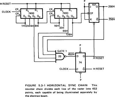
Example of a horizontal sync chain.
(The Textbook of Video Game Logic, Vol. 1; p 50)
Just the same, we'll drive a vertical sync chain by the H RESET signal to count the number of lines, we're sending to the TV (1V, 2V, 4V, 8V, …):
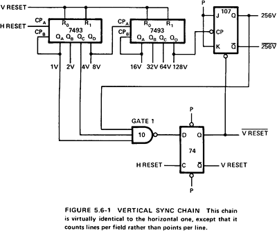
Example of a vertical chain (here, for interlaced video).
(The Textbook of Video Game Logic, Vol. 1; p 59)
What these counter chains actually do look like depends on our the horizontal resolution (as in the number of CLOCK pulses counted by the horizontal sync chain) and, whether it's interlaced or non-interlaced video (for interlaced video, we'd want to count up for the double amount and send just the odd and even lines for a field respectively).
For completeness' sake, we include how the various sync signals are developed (not that we really care for it in this context):
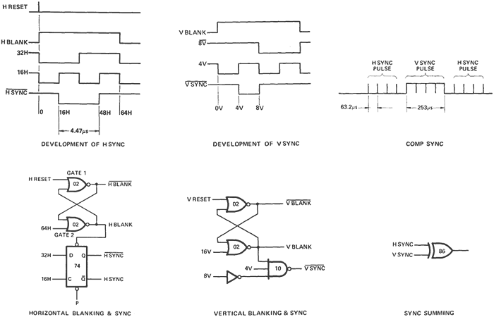
Development of sync signals: Timing (upper row) and in logic gates (lower row).
(The Textbook of Video Game Logic, Vol. 1)
Patterns
Now this gives us an idea, where the beam will be at a given time while tracing the screen and also, when its time to produce the COMP SYNC pulses for composite video, but we haven't produced a picture yet. For this, it may be helpful to view the ouput of basic logic gates (as AND, OR, NOR, XOR) at a slightly different angle, quite similar to the view produced by a video probe (the video game repairman's weapon of choice):
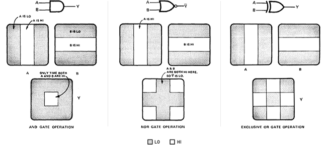
Patterns as generated by basic logic gates.
(The Textbook of Video Game Logic, Vol. 1; pp 9-13; edited N.L.)
If we were, for example, to couple the video signal to the 4H output of our horizontal sync chain, we'd get a vertically striped picture, with stripes 4 raster points wide and separated by yet another 4 raster points. (This is, because, as 1H counts every clock pulse and 2H every second one, 4H will be LO for 4 pulses and HI for the next 4 pulses.) If we were to AND this with 64H, we would mask this stripe for alternating zones of 64 raster positions. Putting this further, we may fix a stripe of any width to any given raster position by a couple of AND and OR gates attached to the clock divisions produced by the sync chain. Such a stripe (or bar) is known as a horizontal window. Just the same, we may define a vertical window by the help of the vertical sync chain. Finally, we arrive at a 2-dimensional window by overlapping horizontal and vertical windows (by a simple AND operation).
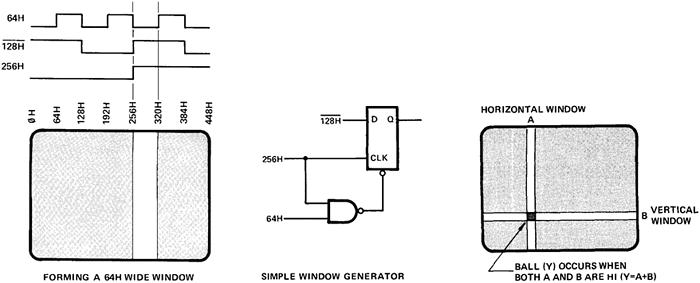
Generating windows from clock pulses.
(The Textbook of Video Game Logic, Vol. 1)
So we know, how we may generate a fixed window of any size on the screen — and with a bit of imagination also, how we may generate more complex patterns, just by a few logic gates. This is fine for the beginning and may be helpful for generating image elements that are fixed to a specific spot, like score displays, as they can be made from vertical bars and horizontal stripes in the fashion of a 7-segment display:
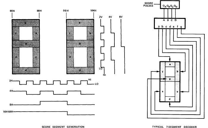
Generating 7-segment style score displays.
(The Textbook of Video Game Logic, Vol. 1)
Moving Objects
Video games are all about moving objects interacting one with another on the screen. We may see already, how we may detect collisions by ANDing the various sync pulses defining the respective windows of two or more objects, but, how may we move those objects across the screen? Considering that this is all about hard-wired logic, we have to admit that we haven't yet the means for this. (We might consider adding some circuitry of sorts to add to the sync pulses and mangle them afterwards, but this would probably equal to constructing an ALU.) The solution is in adding another pair of counter chains for each moveable object. If we reset these counter chains as the beam is crossing a given spot on the screen, the counters will count a full frame and fire just when the beam is on that spot again. Moreover, we'll add a bit of excess to these counter chains and use presetable counter chips for these chains. Such a counter chain is known as a slipping counter chain and it works as follows:
As we're adding excess to the counter chain, say, just a single bit, the chain will use a clock pulse more until it reaches its point of reset. Thus, the chain will fall behind and fire a raster point later than in the previous frame, causing it to slip to the right of the screen. If we provide a preset value of 1, the chain will start already at this offset and will remain in sync with the main counter chains. If we provide a preset of 2, the chain will be slipping to the left as it now finishes a raster position early. The same applies for vertical offsets and vertical motion, only that we're adding or skipping entire lines.
The amount of excess added to a chain defines the maximum amount of motion that may occur between two consecutive frames. This is also the preset value required for the slipping counter chain in order to stay in sync with the main sync chains, also known as stop code. E.g., a chain with a stop code of 7 must be preset by 7 for a motionless object and allows for a maximum motion of 7 positions to the right. Thus we're provided with simple horizontal and vertical motion codes for each of the objects and — as long as we don't care for where we actually are on the screen, but only for relative motion and collision as in most early video games — this is all it needs.
On-screen motion produced by slipping counter chains.
(The Textbook of Video Game Logic, Vol. 1)
Now we can also see, how Computer Space produces the second saucer on the cheap: All it needs is grounding the most significant bit of the vertical counter chain for the display window to fire a display-enable signal and for hit detection. Et voilà, there's the second saucer at a half-frame vertical offset. (Since we're not counting up to a power of two exactly, it may be a bit more complicated in actuality, but you get the idea.)
Sprites / Binary Pattern Stores
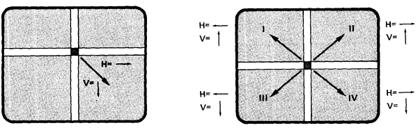
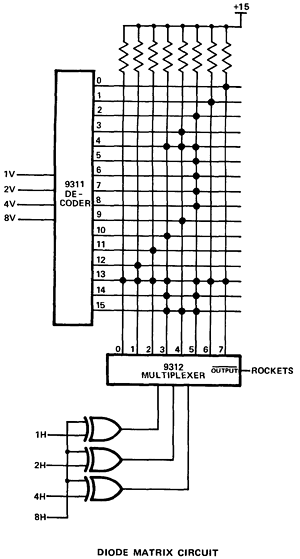
By now, we may have some moving rectangles on the screen, but, still, this is not really what we may expect from a full-fledged video game (while it is pretty much all we need for Pong). What we'd really like to see is an outline, shape or picture representing a specific object, like a rocket ship or a flying saucer. So we have to provide a stored pattern that may be scanned as we advance the beam (by the help of a decoder and a multiplexer). The way to do it on the cheap was by the use of a diode matrix (later also ROMs were used for this, allowing for a greater variety of patterns and images). As the slipping counter chain resets, indicating that we reached our display window, we'll use the first, say 32, pulses in horizontal and vertical direction to scan a matrix of diodes by feeding the horizontal pulses into a multiplexer and selecting vertical lines by a decoder. Wherever there's a diode bridging the respective lines, we'll get a signal, where there is none, the screen will remain blank. (Often, there was just a half-image stored and the second, symmetrical half was produced by inverting the signal on the most significant bit. Likewise, images may be flipped horizontally and/or vertically.)
Example of an image stored in a diode matrix. (Here, a rocket for "Space Race," Atari, Inc. 1973.)
(The Textbook of Video Game Logic, Vol. 1)
And here are the diode matrices as found in Computer Space, one for the saucer, and the rocket ship at 4 different angles (further angles are derived from these):
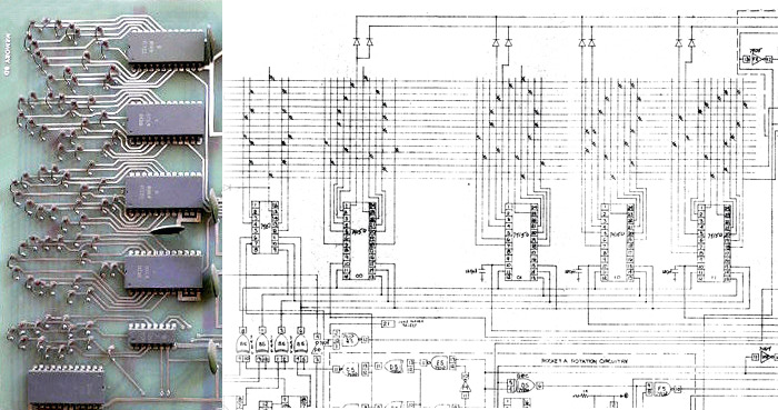
Diode matrices used to define on-screen objects in Computer Space.
As on the board (left; image: pinrepair.com) and as in the schematics (right).
The pairs of diodes above each of the rocket images apparently effect the dots representing exhaust flames.
3) A Cursory Tour to Computer Space Schematics
By now we already know enough to identify some of the principle regions of Computer Space as laid out in the schematics. (No liability or guarantee for correctness, I'm not a hardware guy.) There are just 3 PCBs and the parts count is actually even less as shown in the schematics, as these are frequently splitting 74xx chips (containing usually 3 or more of the simpler components in a single package) into discrete gates or functional units.
The schematics can be found here:
- Original Computer Space manual incl. schematics (Nutting Associates, Inc.)
- Modern, revised schematics (2016)
Here, we go with the original set for the 1-player version.
First, there's the Sync Star Board generating basic sync for the video signal and the final composite signal that is fed into the TV set (a normal, consumer-grade General Electric 'Adventurer II' 15" black & white set, bypassing its tuner by tabbing directly into the circuit board). Also, it provides the background stars and the score display. This board can run on its own, without the other two.
Computer Space, 1-player version, Sync Star Board.
The two chips below the clock are probably providing the logic network for generating the stars.
As we may see, it is fed by the high order counter of the horizontal sync chain and by the vertical sync chain.
The second board is the Motion Board, and we may expect to see some slipping counter chains on this one. In deed, there they are, one for the rocket's missile, one for the rocket ship itself, just a single one for the two saucers and a fourth one for the saucer missile. Moreover there's some circuitry for processing motion codes for the rocket ship and missiles. (The Motion Board contains also analog circuitry for sound not shown in the schematics.)
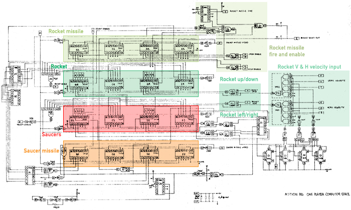
Computer Space, 1-player version, Motion Board.
Vertically stacked we see the slipping counter chains for the various moveable objects.
The vertical interconnections between the counter chains suggest that collision detection is also done on this board.
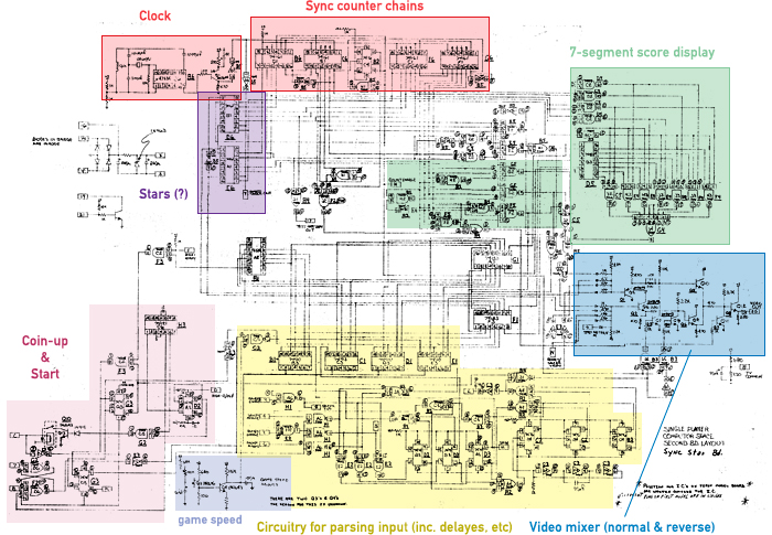
Finally, there is the Memory Board, containing the diode matrices storing the shapes of saucer and rocket and control circuitry for motion parameters. The logic for the saucer is strikingly simple (at least in parts count), suggesting that aiming is done on the motion board (probably by the circuitry at the very left — but this is just my guess).
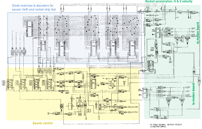
Computer Space, 1-player version, Memory Board.
Here we see the famous diode matrices laying out the shapes of the saucer and the rocket on the top of the schematics.
The saucers' animated rim-dots are probably produced by the ciruitry at the lower left (without liability). The logic controling the saucers is as simple as their patterns of motion. At the right side, we see the comparatively complex logic generating the rocket's velocity parameters from thrust as supplied by the player.
And this was Computer Space.
P.S.: If you were, after all these amazing details, still interested in the poster girl from the Nutting Associates flyer, be informed a) that you're probably beyond help and b) that, while rumors have it that this was none other than Yvette Mimieux, the lead actress in the 1960 George Pal film The Time Machine, it was most likely an anonymous employee of The Brass Rail bar, a favorite hangout of computer engineers in the Sunnyvale area. Compare this page at computerspacefan.com.
4) Obligatory Historical Notes without no Description of Computer Space May be Considered Complete
Computer Space was famously the first coin-operated arcade video machine put on location, in August 1971, beating Galaxy Game by Bill Pitts and Hugh Tuck (essentially display cabinets hooked up to a PDP-11 running multiple instances of Spacewar! and availbale to visitors of the Tresidder student union building at Stanford University only) by a month. Inspired by Spacewar! as well, Nolan Bushnell first considered a similar solution as the one chosen by Pitts and Tuck for Galaxy Game, using a General Data Nova computer. The game changing moment (lame pun, but intended) came, when this plan proved to involve far more resources than bearable for a commercial game that was supposed to earn back the investments by quarters. Looking for another solution, Bushnell teamed up with Ted Dabney (being colleagues at HP) to develop the game in a much cheaper, still digital technology under the name of Syzygy Engineering. Eventually, Bushnell partnered with an established vendor of amusement machines, Nutting Associates, Inc., who had shown serious interest in the project, for polishing and marketing the game (which was a mild, but not wild success — so we're not talking about a "disruptive product", rather, electro-mechanical arcade games coexisted with early video games for a few years thereafter). The rest is history…
*****
And Now for Something Completely Different
 There are some — we may call them the Church of True Video Games (CoTVG) — who believe that only those machines which are directly manipulating the electron beam of a CRT in a time-based manner, just as we've seen it above, without any help of any kind of store, raster processor or any other intermediary of sorts, may be called true video games.
Now, the CoTVG is not to be made fun of, because they have a Spanish Inquisition of their own, which will be mercilessly probing any game, aspiring to the sacred term of video game, that doesn't meet their criteria of orthodoxy. (E.g., even the very first digital video game, Spacewar!, doesn't find mercy in their eyes, which is also, why we're always putting the qualifyer "digital" in front, whenever we dare to address this game. After all, you have to expect the Spanish Inquisition.)
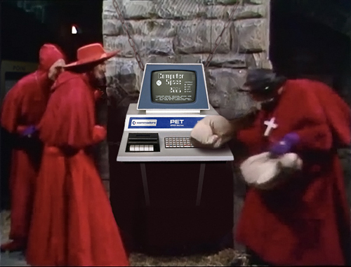
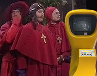
The Spanish Inquisition of the CoTVG probing our humble project mercilessly with soft cushions.
(Base image: Monty Python; edited, N.L. 2017.)
The Spanish Inquisition of the CoTVG has come up with an elaborate torturing device to teach adventurous software developers of their hubris, make them admit their fallacy and eventually submit to the authority of the CoTVG, the Vicious Cushion Slapper 2600. — "Racing the Beam" is, what they are sardonically calling this cruel procedure.
So, let's talk about the VCS.
The Atari VCS (Video Computer System™) / Atari 2600
Just like the Commodore PET, the Atari Video Computer System™ or short VCS is turning 40 this year. Developed under the code name "Stella" by Atari's R&D division Cyan Engineering in the Northern California Sierra Nevada foothills, in Grass Valley, the VCS (or, as of 1982 and thereafter, the Atari 2600) was released in September 1977 in order to make video games a home appliance. With some success, as we dare say, as it became, with about 30 million units sold, one of the most popular electronic home entertainment products ever.
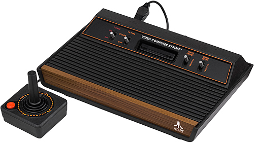
The Atari VCS, four-switch "wood veneer" version as produced between 1980 and 1982.
(Image: Evan-Amos / Wikimedia, public domain.)
What may seem like an intricate torturing device for software developers, rather makes perfect sense in the light of the technology used by early video games, as we have been investigating above, by stripping down the functionallity to its core by a strict discipline in cost reduction and at the same time generalizing it by adding software control. The VCS consists of just 3 major electronic components, a video processor, the TIA (Television Interface Adaptor), a MOS 6507 microprocessor (a cost reduced version of the 6502 with just 13 address lines and no interrupt pins) and an off-the-shelf PIA interface chip (also known as RIOT), the three of which reportedly came at a cost of just $12 in total.
The heart of the VCS is the TIA, a custom chip abstracting the workings of a video game to its strictest core. The TIA has no notion of any vertical extent, it just continuously processes a raster line of composite video and fires it to any
Racing the Beam
You may have heard or read this term before, but, what is it really all about? Let's start with the TIA.
The TIA has all it needs to put some of the most popular Atari games to date onto the screen of a home TV, like Pong or Tank. For this purpose, the TIA features so-called player / missile graphics, basic sprites without any notion of
But what is exactly a pixel for the TIA? As we already know, there are 262 lines in a NTSC field — and the VCS features non-interlaced video only, so we're dealing with just odd fields at 60 Hz. The TIA is clocked at 3.58 MHz, dividing a single raster line into 228 pixels, which the TIA produces and delivers on the spot to the attached
In order to position these "sprites" (this term hadn't yet been coined, as it was only to be introduced with the C64 and its MOB-graphics), the TIA featured internal counters, the equivalent of a horizontal counter chain. By strobing a register (i.e., writing any value to it), these counters can be reset and the respective object's position will be fixed to the current position of the raster beam. Likewise, there are registers, analogous to the slipping part in a slipping counter chain, for moving an object relatively to the left or the right by up to 7 pixels (the equivalent of a stop code of 7). While the strobe of the counter reset will take effect immediately (that is, with a delay of a few pixels), any offsets provided in the "slip" registers will be applied each time and only then, when yet another special register is strobed. This particular strobe has to be applied on the very beginning of a scan line and no other positioning may be applied immediately thereafter.
While this provides us with the functionallity of an early video game, reduced to the processing of a single raster line, but with enhanced color graphics, we need some facillity of feeding this beast. This is, where the 6507 processor joins the game. Because of its just 13 address lines, the 6507 can "see" only a reduced amount of address space, with the other chips and the 128 bytes of RAM at the "bottom" and 4K of ROM to be provided by a cartridge (mirrored over the internal 64K address space). Otherwise, it's internally identical to the popular 6502 processor.
The 6507 processor is clocked by the TIA at a third of its own clock rate. This results in a clock rate of 1.19 MHz for the 6507, 20% faster than the home computers running the 6502 at the 1MHz standard speed (with the notable exception of the BBC Micro), rendering the VCS quite a beast computationwise. The 6502/6507 features variable instruction lengths and cycle counts, where an instruction takes at least 2 and up to 7 cycles. (Moreover, extra cycles may occur as page bounderies are crossed or different paths are taken by a branch instruction). The only means of synchronizing the 6507 with the raster line produced by the TIA is by strobing its WSYNC register, which will cause the TIA to halt the processor until the beginning of the next scan line. This results in the following, basic timing diagram:
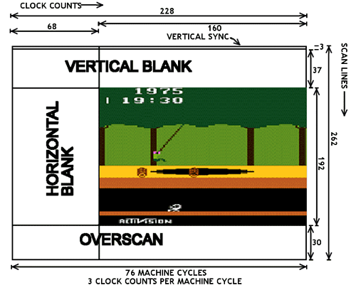
Atari VCS playfield timing, pixel rates and 6507 cycles.
(Image: AtariAge, based on the "Stella Guide" VCS developer documentation.)
This still looks reasonable: While we have to manage vertical timing and V SYNC ourselves, we also have to implement the vertical slipping counter chains in software. Vertical timing is managed in a big loop, called a kernel: We'll start with 3 H SYNCs for the V SYNC signal and then we may spend plenty of instructions during the remaining vertical blank of 37 horizontal lines. We may do some processing here, and just before we enter the visible screen area, we'll position our sprites. (More on this later.) Then there's a tight loop managing 192 lines of display area, and then we'll shut off the beam for another 30 lines of overscan (time for more general processing, like checking hit states, etc), before we start over for the next frame.
Positioning the sprites is somewhat awkward: For horizontal positioning, we'll have to wait for the right pixel (TIA clock cycle) and then we'll strobe the reset register for the respective object. Sounds easy, but there are 3 pixels per processor cycle and the average instruction takes 3 to 4 cycles. — In fact, the minimal delay loop is 5 cycles per iteration, providing us a precision of just 15 screen pixels (5 × 3 TIA clock cycles)! — Mhm. — Thankfully, there's also a 15 bits span of variance in the horizontal offset movement registers, and with a bit of trouble and basic arithmetics we can manage to position a sprite precisely for the frame to follow.
Vertical positioning and the selection of sprites to display (as well as theIr pattern and, maybe, also their color) is done during horizontal blank, lasting for just 68 pixels (or TIA clocks). This gives us about 20 odd 6507 instructions. Considering that an indexed lookup is 5 to 7 cycles and sending the respective value to the TIA is yet another 2 cycles and we'll have to check positions somehow, this is not much, but just enough for a basic game. But we're soon reaching the limits as we're trying to control multiple objects. This is, where most games resolve to a so-called 2-line kernel, halving the visible resolution. (But not necessarilly the resolution in vertical positioning, as the TIA also provides one-line delays on a per-object basis.) The other solution to the problem is in interlacing and managing sprites in alternating frames, which may also be used to bring more than the two player sprites supported by the hardware onto the screen.
Ticks & Tricks
Now, a software developer is a biped bag of tricks and is always eager to challenge the very boundaries set by the hardware. Can't we do any better? Let's say, change the background pattern midways, to display something different on the right side of the screen? Yes, we can! — And this is, we're we are racing the beam, as we have to count the instruction cycles since the last horizontal sync (WSYNC) in order to know, when exactly we are to send the respective values to the TIA (but again, there's the 3 pixels per cycle limit in resolution and some odd pixels for the TIA to put the change into effect). With early success granted easily (playfield graphics are 4 times the pixel width!), hubris is never that far away, and this is, where the VCS is starting to teach its lessons of humbleness.
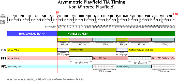
Timing diagram for switching playfield graphics (TIA registers PFO, PF1, PF2) mid-screen on the VCS.
(Image: AtariAge.)
For example, we may want to implement Computer Space, since the VSC is still lacking a port of its own. We'll use a player sprite for the rocket, another one for the saucer, which is replicated at an vertical offset easily. And the two missiles provided by the TIA are just what we need for Computer Space. The trouble starts with the 8 pixel limit for the width of a player sprite, as we'll need at least 9 of them to display something with a faint semblance of the original saucer graphics. No need to give up here, as there's still the ball, which we may use for the 9th pixel. — Done.
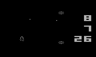
Pixel-perfect mockup of Computer Space for the VCS.
(© 2017 N. Landsteiner, www.masswerk.at)
For the scores and time display, we'll have to race the beam in order to setup the playfield graphics (which are just perfect in resolution for a 7-segment display), but that's nothing out of the order. Fine?

Our mockup adjusted for a pixel aspect ratio of 1:1.2 as found on TV sets.
Yeah, the rocket may be a bit crude, but you just can't have it all. While we may be able to manage the sprite selection for each scan line for all the 5 objects with a few tricks, the real trouble starts with the background stars. Usually, the ball is used for this, but we're using it already for the saucer, and repositioning is out of question, as we have also to wait for just the right time to manage the score displays. Moreover, we haven't provided for the exhaust flames yet, and again, we're out of pixels with the player graphics and the ball is already in use. As switching to a 2-lines kernel (to gain extra time for repositioning some of the sprites) isn't an opportunity, with regard to the graphics we want to display, we're soon running out of options. In fact, we may have to change our plan to something more like Space War for the Atari VCS (1978), which isn't really good enough for anything conveying the charms of the original game.
Moral
Remarkably, we were able to implement the game on the early 1960s PDP-1, running at 200 KHz (a 6th of the 6507 in the VCS) at 1024 × 1024 pixels, even with some extras, like a background starfield animated in a parallax effect and fancy explosion graphics. And, while we had to wait for the display, we managed to run the games at the amazing frame rate of 60 Hz and had still some extra cycles to burn in a delay loop. On the other hand, on the VCS, using a processor at 6 times the speed, we are constantly falling behind the display, are stumbling along, always in need for even more resources — and, in fact, we're not able to implement even the most basic rendition of the game. Bummer.
The lesson taught by the VCS is, what an intimidating beast the cathode beam of a 60 Hz raster display is to a general purpose processor in the single-Megahertz-range.
This isn't only illustrating nicely, why X/Y displays were the weapon of choice in the early days of visual computing, it also teaches, why we really have to be grateful for any dedicated display processing as provided by the PET, even, if it is to deliver crude character graphics only. (And character graphics are a great deal, compared to X/Y graphics, apart from anything regarding fancy visuals.) We'll happily pay the price and deal with these restriction, which are so completely different from the timing issues seen on the VCS. Also, restrictions are fun, remember?
But this is yet another episode …
— Stay tuned! —
*****
P.S.: Once again, we may want to rephrase a famous argument by Elon Musk:
Considering the decline in video game graphics and the computing power required in just a single decade, from Spacewar! over Computer Space to Pong (and from there to the VCS), and extrapolating this into the future, we may doubt that there will be electricity at all, 40 years from now.
;-)
*****
▶ Next: Episode 3: A Starry Afternoon
◀ Previous: Episode 1: Character Graphics!
▲ Back to the index.
April 2017, Vienna, Austria
www.masswerk.at – contact me.
— This series is part of Retrochallenge 2017/04. —