Episode 5: Sync!
Were we finish our implementation of the "Sync Star Board" in software. After considering the proper order of execution, we're ready to serve reverse video and only the best 7-digit displays, while avoiding frying the circuitry too crisp!
Holy Capacitor, Batman, we're back again, doing some on the Personal Computer Space Transactor 2001!
This time we're going to implement the rest of the functionality of the Sync Star Board of the original Computer Space. Since, we have some stars already, it will be about the "sync" part, as well as score and time displays, and video mixing.
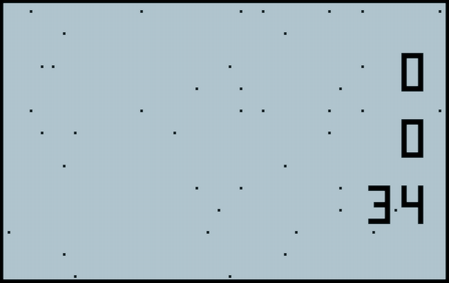
For spoilers, this is what we eventually achieve:

Our soft implementation of the Sync Star Board on the PET 2001.
(Emulation, exported screenshot.)
▶ See it live in in-browser emulation.
Video Sync, Halt & Catch Fire
As opposed to later 6502 machines, the original PETs (board #1) used rather slow (static) video RAM (located in the normal address space at $8000), clocked at 1MHz, the same speed as the central processor clock. To take care of potential race condition when both the CPU and the video circuitry were to access the video RAM at the same time, the CPU was given precedence, resulting in invalid video data and subsequently "snow" on the screen in case of a collision. In order to prevent this snow on the screen, the PET's BASIC waits for the V BLANK signal (generated by the master timing circuitry in combination with the VIA chip) whenever there is a print command and updates the video RAM only when the screen is blank. (As a result, printing onto the screen in BASIC is rather slow on the original PETs.) — A scheme, we should consequently adhere to in any implementation of our own to maintain any video output.
Compared to basic video logic in general and the oddities of the Atari VCS in particular, as we explored them in Episode 2, this gives quite the reverse picture, regarding general application timing:
| System/ Video Phase | Atari VCS | PET 2001 |
| Visible | Display logic ("Racing the beam") | Business logic |
| V BLANK | Business logic | Display logic |
Eventually, PETs came with faster, dynamic RAM, putting an end to any potential collisions. Thus, later ROM revisions feature a faster PRINT command, which will not wait for V BLANK (resulting in snowy video, when used with an early PET). Nevertheless, we'll go for V BLANK timing anyway, since we're targeting the PET 2001 in general.
Moreover, the changes in ROM brought also some changes in zero page addresses used by the system, meaning, we have to care for these variation all the same. In particular, this is the IRQ vector. All (normal) interrupts are handled by the 6502 by a jump vector at $FFFE, which in turn points to the IRQ vector set up by the various ROM revisions in different ways.
PET IRQ vectors:
- ROM 1.0 (PET 2001 8K):
$0219(decimal 537) - ROM 2.0+ (PET 2001 16K, 32K, upgraded revisions):
$0090(decimal 144)
Notably, all IRQs occuring in normal operations are handled by the same interrupt routine on the PET, and there is also only the V BLANK signal that generates an IRQ, when the PET is in normal execution mode. Hence, 60 times a second, the PET will tick its internal clock, update the screen RAM according to any PRINT commands and scan the keyboard for any keys pressed.
It's also this peculiar bottleneck in I/O operations that lead to PET's very own halt-and-catch-fire instruction:
The Killer Poke
It didn't take long and developers discovered that there was another way to force the PET into a V BLANK, allowing for immediate PRINT operations and a substantial speed-up of BASIC games: There's a signal (PIA 1, CA2), which forces a the video to blank and subsequently generates a system interrupt. Since all ports are mapped to the address space, this feature is also available to any program running on the PET, namely by setting bit 5 of $E842 or decimal 59458 (VIA Port B: DDRB, normally %00011110), the original Speed Poke:
POKE 59458, PEEK(59458) OR 32
or, simply
POKE 59458, 62
While this improves BASIC performance by a great deal with boards #1 and does nothing with boards #2 and upgradet RAM and ROM, there's a tiny issue with boards #3, featuring the new CRTC video chip: Here, the very signal has direct affect on the video logic, frying the monitor's flyback transformer by forcing it into an irregular phase, thus transforming the former Speed Poke into the infamous Killer Poke. — Oops!
Not with a PET 2001, but take care of those 12" screen machines…
Eventually, Commodore took care of the issue by replacing the TTL + analog video logic by yet another chip, which now restricts itself to just the halt part in halt-and-catch-fire, skipping the fire. With these revisions, according to the Commodore PET FAQ, "the screen starts to warp after about the third line and the display stops around the fifth, the keyboard is also unresponsive. When a PET is in this mode, the only solution is to turn it off" — and, in case you're not sure about your board revision, — "FAST!"
Race for Screen Time
However, in order to service all machines and to prevent any damage to real hardware, we'll have to wait for a regular interrupt and maintain the screen output in our own interrupt handler, which will in turn hand over to the system interrupt routines. Thus, we'll have to do any screen logic during V BLANK (as shown in the chart above).
And just as a reminder, there isn't that much time, since the beam is racing on mercilessly. To get an idea, just compare this match between the 6502 executing a minimal program on the C64 (running at the same 1MHz as in the PET) against the video beam (at a resolution of 320 × 200 + borders @ 60Hz, similar to the PET 2001: 40 × 25 characters of 8 × 8 pixels = 320 × 200 @ 60Hz):
; Flicker border and background (C64, <https://csl.name/post/c64-coding/>)
.loop
  inc bgcolor         ;(6 cycles)
  inc bordercolor     ;(6 cycles)
  jmp .loop           ;(3 cycles)
C64 versus the video beam: Strips of background color correspond to iterations of the color loop.
(Image: Christian Stigen Larsen, 2016.)
Implementation
The Sync Star Board doesn't only handle the sync, it also does the final video mixing (including reverse video mode) and the 7-segement displays of the scores and play time. So we have to spend a few thoughts on this. Especially, what will be our stacking order as we're mixing our video planes, of which there are 3 in general: The background stars, the scores, and the various character sprites. Particularly, when will we have to redraw any of these parts and which one will have precedence?
The background is a rather a nobrainer: We'll generate it once and restore it on the fly, as any of it is revealed by the movements of an object. But, what about the scores? Are they ging in front of the sprites or below them, and when are we going to repaint them? Given the low resolution of our character display, we're going to put the sprites on top, otherwise, there won't be any way to know, if any of the sprites is obscured by a score, since actual mixing is not an option. (There will be only this character or the other, bot never both of them at the same time in the same position.) By this, we also take care of a possible race condition, when a moving sprite reveals part of a numeral while the score in the background has changed in the meantime: We'll simply redraw the scores everytime, we have to redraw the sprites.
This gives us the following order of video related operations:
- Draw background (once).
- Restore any background characters (revealed by a moving sprite).
- Redraw scores (if there is a repaint at all).
- Draw sprites in current position (if moved).
While we're not dealing with the sprites in this episode, we have the general plan of storing any restore and drawing commands in a queue, provided as alternating screen codes and RAM addresses, which are rather simple and fast to loop over. This way, we may handle all game logic asynchronously without any concerns to the logic we're implementing here. The only means of communication will be two flags, one requesting a repaint and another one for the main program to wait for the next IRQ being processed.
Reverse video will be handled by our sync-mix logic, by the means of simple masking byte, which will be XOR-ed with the screen code in order to flip bit 7 (for reverse video) or leaving it as-is.
Finnally, we'll implement a simple procedure to flip this mask together with any screen content.
Setup
First, we'll have to make sure, we're not in BCD mode, otherwise our arithmetics may be a bit off. Here, we also introduce our repaint flag (by setting it to zero, we're making sure that the interrupt handle, we're going to implement, won't trigger prematurely):
                * = $044C
                ; reset / setup
                cld                  ;clear BCD flag
                lda #0               ;clear our repaint flag (for IRQ routine)
                sta fRepaint         ; to avoid any race conditions
BTW, these are allt the flags and zero page pointers we're using in this edition:
; symbols

ticksPerSecond = 60  ;60: time in game corresponds to NTSC timing

; zero-page

fGameRunning = $23    ;0: attract, 1: active (unused)
fIRQ  = $24           ;flag to synchronize irq operations
fRepaint = $25        ;flag for video rendering/irq control
ticks = $26           ;ticks counter
videoMask = $27       ;0: normal, $80: reverse (xor-ed)
IRQVector = $28       ;backup of original irq vector (2 bytes)
PT1 = $50             ;versatile pointer (2 bytes)
PT2 = $52             ;versatile pointer (2 bytes)
Now it's time to capture the IRQ vector. But which one? You'll bet, both (regarding ROM revisions).
In ROM 1.0 the IRQ vector will be at $0219 and in newer ROMs at $0090. I don't know much about ROM 1.0, but I do know that the IRQ-vector will point to an address at $Exxxx in newer ROMs (ROM 2.0, ROM 4.0) and that there's probably a low value in the address of the hi-byte of the newer IRQ vector using ROM 1.0. So we'll check for an value of $Ex in $91, and decide on this. Whatever is currently in the IRQ vector, we'll move to a backup to be used as the exit for our own IRQ routine, the address of which we'll install instead in the IRQ vector.
Also, we have to make sure that we're not trapped midways by a system interrupt, now wandering off into the unknown, by bracketing this construct in "SEI" (set interrupt disable flag) and "CLI" (clear interrupt disable flag) instructions.
setup           ; setup IRQ vector
                sei                  ;set interrupt disable flag
                lda $91
                and #$E0
                cmp #$E0             ;is it ROM 2.0 or higher?
                bne .rom1            ;no, it's ROM 1.0
.rom2           lda $90              ;save IRQ vector
                sta IRQVector
                lda $91
                sta IRQVector+1
                lda #<irqRoutine     ;and install our own
                sta $90
                lda #>irqRoutine
                sta $91
                jmp .setupDone
.rom1           lda $219             ;same vor ROM 1.0
                sta IRQVector
                lda $21A
                sta IRQVector+1
                lda #<irqRoutine
                sta $219
                lda #>irqRoutine
                sta $21A
.setupDone      cli                  ;reenable interrupts
Auto-configure done. (We may extend this code later to set up further ROM-specific addresses.)
Now we need a little piece of code to initialize the game, introducing also variables for scores and time (score1: rocket, score2: saucer, time1: time, least decimal digit, time2: tens of seconds), which we're all resetting to zero:
init
                lda #0
                sta fGameRunning     ;not used here, but anyway
                sta videoMask        ;normal video (white on black)
                sta fRepaint         ;no repaint while we're
                jsr background       ; drawing the background
                lda #0
                sta score1
                sta score2
                sta time1
                sta time2
                sta ticks
                lda #1
                sta fRepaint         ;request a repaint
                sta fIRQ             ;set to 1 in order to wait

;...

; variables

score1          !byte 0
score2          !byte 0
time1           !byte 0
time2           !byte 0
7-Segment Digits
Before we continue with our main logic, we should figure (lame pun intended) how we may draw our scores and time display. We already know, what it'll look like (compare Episode 1). The data for a digit goes into 8 bytes (2 columns × 4 rows), and we won't care whatever background may be below.
This is, what the data of our digits looks like, including a simple table of offsets for the start address of any respective block of data (for easy reference by indexed addressing):
digits
                ;0
                !byte $62,$62            ; ▄ ▄
                !byte $61,$E1            ; ▌ ▐
                !byte $61,$E1            ; ▌ ▐
                !byte $FC,$FE            ; ▙ ▟

                ;1
                !byte $20,$6C            ;   ▗
                !byte $20,$E1            ;   ▐
                !byte $20,$E1            ;   ▐
                !byte $20,$E1            ;   ▐

;               ...

                ;9
                !byte $62,$62            ; ▄ ▄
                !byte $61,$E1            ; ▌ ▐
                !byte $E2,$FB            ; ▀ ▜
                !byte $20,$E1            ;   ▐

digitOffsets
                !byte 0, 8, 16, 24, 32, 40, 48, 56, 64, 72

;Note: Unicode block characters in comments may be off, depending on the font.
Now the nifty part, drawing a given numeral at a given screen location:
drawDigit ;draws a digit (screen address in PT1, digit in Y register)
                ldx digitOffsets, y  ;load bytes offset into digits data in x
                ldy #0          ;clear y (used as col offset)
                lda #4          ;rows to do
                sta PT2         ;set it up in PT2 (a single byte)

.dgRow          lda digits, x   ;load the screen code
                eor videoMask   ;adjust for normal/reverse video
                sta (PT1), y    ;store it
                inx             ;next byte
                iny             ;next col
                lda digits, x
                eor videoMask
                sta (PT1), y

                dec PT2         ;decrement row count, are we done?
                beq .dgDone
                inx             ;next byte
                dey             ;reset y (col offset) to zero
                clc             ;and increment PT1 by a screen line
                lda PT1
                adc #40
                sta PT1
                bcc .dgRow
                inc PT1+1
                jmp .dgRow
.dgDone         rts
We simply set up the starting screen adderss in a zero page pointer and compute the offset into our digits data from the value provided in the Y register by an indexed look-up into our digitOffsets table. For the indexed adressing, it's important to have the index into the screen RAM in the Y register, leaving only the X register for the data index. The rest is a matter of a simple loop, applying a simple increment for a column or data byte and an increment by 40 for the next screen line.
The XOR in "eor videoMask" takes care of the video mode: If the value in videoMask is zero, it'll do nothing, if $80, it'll flip the most significant bit of the screen code, we're going to store, for reverse video.
Importantly, the indirect Y-indexed addressing (as in "sta (PT1),y") works only, if our 2-bytes pointer PT1 is located in the zero page.
***
(Note on indirect addressing on the 6502: The effective address of sta (PT),y is the double byte address in PT and PT+1 plus the offset in the Y register. This mode is only supported for the Y register and not for the X register. Generally, parentheses in the address part indicate indirect addressing in 6502 assembler. Indexed indirect — as in sta (PT,x) — and indirect indexed — as in sta (PT),y — addressing modes are valid for zero page addresses only.)
***
Calling the 7-segment digit routine is a matter of setting up the value in Y and the screen address of the top left character position in PT1 (2-byte address):
; screen locations of score and time numerals
screenAddressScore1 = $8000 + 4*40 + 36
screenAddressScore2 = $8000 + 10*40 + 36
screenAddressTime1 = $8000 + 16*40 + 36
screenAddressTime2 = $8000 + 16*40 + 33

drawScores ;draws scores and time display
                ldy score1                  ;value in Y
                lda #<screenAddressScore1   ;screen addr, lo byte
                sta PT1
                lda #>screenAddressScore1   ;screen addr, hi byte
                sta PT1+1
                jsr drawDigit               ;call drawing routine

                ; same for score2
                ; same for time1
                ; same for time2

                rts
Video Modes
We've already seen how videoMask is used to control the video mode of the digits display. Here is a routine to revert the screen and flip the value in videoMask, regardless of the current state. (So it'll be reverse, if it was normal, or else will flip back to normal.)
revertVideo ;reverts the screen video
                lda videoMask
                eor #$80
                sta videoMask

                ldx #24
.rvRow          lda screenLinesLo, x
                sta PT1
                lda screenLinesHi, x
                sta PT1+1
                ldy #39
.rvCol          lda (PT1), y
                eor #$80
                sta (PT1), y
                dey
                bpl .rvCol
                dex
                bpl .rvRow
                rts
The flipping is done by the XOR in "eor #$80", both for the video-mask and the individual bytes of screen memory. The loop over the screen memory is similar to the one we used for the background.
Here, we don't care about video timing, because this will probably be part of an explosion and any snow will rather add to the effect. Thus we may do it anytime, outside the interrupt handler and take what ever time it may need.
Interrupt Handling
Now we may finally address the IRQ handler. Here's our to-do list:
- Increment ticks.
- Check for repaints (currently just redraw the digits).
- Clear repaint and irq-wait flags.
- Jump to system interrupt routine.
And this is what it looks like in code:
; IRQ handling

irqRoutine

                inc ticks            ;manage time

.checkRepaint
                lda fRepaint
                beq .irqDone
                jsr drawScores

.irqDone
                lda #0
                sta fRepaint
                sta fIRQ
                jmp (IRQVector)
Note: We should really save and restore the CPU registers (AC, X, Y), but because, our main task exucutes in shorter time than there is between system interrupts, it is not an issue here.
Job Loop
Anything left to-do? Ah, what about the actual main loop?
Currently, there isn't much to do. We have to display the digits once (already taken care of by setting the repaint-flag to 1), but else, there isn't much on the agenda. For test purpose, we may count the time and manage it's display, and we may also test our reverse video logic by flipping the video mode each time, we increment the high-digit counter of the play time. And since this is just a test, we simply start over, when ever we happen to reach 100 seconds.
; main job loop
loop
                lda fIRQ             ;wait for interrupt handler
                bne loop

                ; manage time
                lda ticks
                sec
                sbc #ticksPerSecond  ;has a second passed?
                bcc .loopIter        ;no, skip the rest

                sta ticks            ;store ticks, now reduced by a second
                inc time1
                lda time1
                cmp #$0A             ;have we arrived at 10?
                bne .loopScoresFinal ;no, skip

                jsr revertVideo      ;just a test, flip video every 10 secs

                lda #0               ;reset 1s to zero
                sta time1
                inc time2            ;increment 10s
                lda time2
                cmp #$0A             ;have we arrived at 10?
                bne .loopScoresFinal ;no, skip
                lda #0               ;(game over)
                sta time2            ; here: just reset 10s and continue

.loopScoresFinal
                lda #1              ;request a repaint
                sta fRepaint

.loopIter       lda #1
                sta fIRQ            ;set IRQ-wait flag
                jmp loop            ; and start over
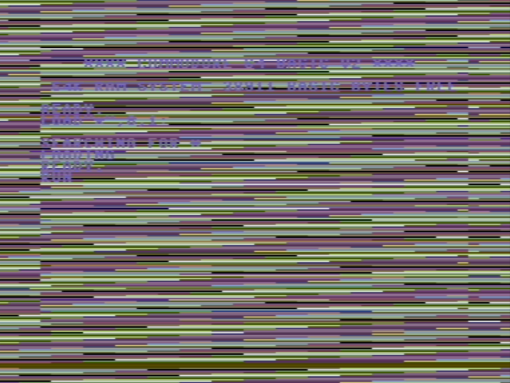
Lo and behold, our reverse video is working (reverse for each odd decade of seconds):
Our test in reverse video.
▶ Try it in in-browser emulation.
Note: In order to test the program with ROM 1.0, reset the virtual PET and switch to "ROM1" in the menu below the screen. The prg-file will still be mounted. Now type « LOAD "*",8 » + RETURN and press RUN/STOP on the virtual keyboard, when prompted. Type « RUN » and hit RETURN, there you go with ROM 1.0 …
— Yay, our ROM detection works as intended.
Code Listing
And here is our code, in its entirety:
△! Caution, the interrupt routine used in this example does not preserve registers! (Not an issue here, since the main task loop is shorter than the time passed between interrupts.)
!to "sync.prg", cbm  ;set output file and format

; symbols

ticksPerSecond = 60  ;60: time in game corresponds to NTSC timing

; zero-page
; BASIC input buffer at $23 .. $5A may be reused safely (cf, PET 2001 manual)

fGameRunning = $23    ;0: attract, 1: active (here, unused)
fIRQ  = $24           ;flag to synchronize irq operations
fRepaint = $25        ;flag for video rendering/irq control
ticks = $26           ;ticks counter
videoMask = $27       ;0: normal, $80: reverse (xor-ed)
IRQVector = $28       ;backup of original irq vector (2 bytes)
PT1 = $50             ;versatile pointer (2 bytes)
PT2 = $52             ;versatile pointer (2 bytes)

; intro

; insert a tiny BASIC program, calling our code at $044C (1100)
;
; 10 REM PERSONAL COMPUTER SPACE
; 20 REM TRANSACTOR 2001 (NL,2017)
; 30 SYS 1100

                * = $0401

                !byte $1F, $04, $0A, $00, $8F, $20, $50, $45 ; $0401
                !byte $52, $53, $4F, $4E, $41, $4C, $20, $43 ; $0409
                !byte $4F, $4D, $50, $55, $54, $45, $52, $20 ; $0411
                !byte $53, $50, $41, $43, $45, $00, $3F, $04 ; $0419
                !byte $14, $00, $8F, $20, $54, $52, $41, $4E ; $0421
                !byte $53, $41, $43, $54, $4F, $52, $20, $32 ; $0429
                !byte $30, $30, $31, $20, $28, $4E, $4C, $2C ; $0431
                !byte $32, $30, $31, $37, $29, $00, $4A, $04 ; $0439
                !byte $1E, $00, $9E, $20, $31, $31, $30, $30 ; $0441
                !byte $00, $00, $00 ; $0449 .. $044B


; main

                * = $044C
                ; reset / setup
                cld                  ;clear BCD flag
                lda #0               ;clear our repaint flag (for IRQ routine)
                sta fRepaint         ; to avoid any race conditions

setup           ; setup IRQ vector
                sei                  ;set interrupt disable flag
                lda $91
                and #$E0
                cmp #$E0             ;is it ROM 2.0 or higher?
                bne .rom1            ;no, it's ROM 1.0
.rom2           lda $90              ;save IRQ vector
                sta IRQVector
                lda $91
                sta IRQVector+1
                lda #<irqRoutine     ;and install our own
                sta $90
                lda #>irqRoutine
                sta $91
                jmp .setupDone
.rom1           lda $219             ;same vor ROM 1.0
                sta IRQVector
                lda $21A
                sta IRQVector+1
                lda #<irqRoutine
                sta $219
                lda #>irqRoutine
                sta $21A
.setupDone      cli                  ;reenable interrupts

init
                lda #0
                sta fGameRunning
                sta videoMask
                sta fRepaint
                jsr background
                lda #0
                sta score1
                sta score2
                sta time1
                sta time2
                sta ticks
                lda #1
                sta fRepaint
                sta fIRQ


; main job loop
loop
                lda fIRQ
                bne loop
                ; manage time
                lda ticks
                sec
                sbc #ticksPerSecond  ;has a second passed?
                bcc .loopIter        ;no
                sta ticks
                inc time1
                lda time1
                cmp #$0A
                bne .loopScoresFinal
                jsr revertVideo      ;just a test, flip video every 10 secs
                lda #0
                sta time1
                inc time2
                lda time2
                cmp #$0A
                bne .loopScoresFinal
                lda #0
                sta time2
.loopScoresFinal
                lda #1
                sta fRepaint

.loopIter       lda #1
                sta fIRQ
                jmp loop


; IRQ handling

irqRoutine

                inc ticks            ;manage time

.checkRepaint
                lda fRepaint
                beq .irqDone
                jsr drawScores

.irqDone
                lda #0
                sta fRepaint
                sta fIRQ
                jmp (IRQVector)


; subroutines

background ;fills the screen with stars
                ldx #24
.row            lda screenLinesLo, x
                sta PT1
                lda screenLinesHi, x
                sta PT1+1
                ldy #39
.col            jsr getStar
                sta (PT1), y
                dey
                bpl .col
                dex
                bpl .row
                rts


getStar ;returns a background screen code (in AC) for row X, col Y
                lda starMaskY, x
                beq .blank
                and starMaskX, y
                beq .blank
                lda #$2E ; return a dot
                rts
.blank
                lda #$20 ; return a blank
                rts


; score and time display
; screen locations of score and time numerals
screenAddressScore1 = $8000 + 4*40 + 36
screenAddressScore2 = $8000 + 10*40 + 36
screenAddressTime1 = $8000 + 16*40 + 36
screenAddressTime2 = $8000 + 16*40 + 33

drawScores ;draws scores and time display
                ldy score1                  ;value in Y
                lda #<screenAddressScore1   ;screen addr, lo byte
                sta PT1
                lda #>screenAddressScore1   ;screen addr, hi byte
                sta PT1+1
                jsr drawDigit               ;call drawing routine

                ldy score2
                lda #<screenAddressScore2
                sta PT1
                lda #>screenAddressScore2
                sta PT1+1
                jsr drawDigit

                ldy time1
                lda #<screenAddressTime1
                sta PT1
                lda #>screenAddressTime1
                sta PT1+1
                jsr drawDigit

                ldy time2
                lda #<screenAddressTime2
                sta PT1
                lda #>screenAddressTime2
                sta PT1+1
                jsr drawDigit
                rts

drawDigit ;draws a digit (screen address in PT1, digit in Y)
                ldx digitOffsets, y
                ldy #0
                lda #4          ;rows to do
                sta PT2
.dgRow          lda digits, x
                eor videoMask   ;adjust for normal/reverse video
                sta (PT1), y
                inx             ;next byte/col
                iny
                lda digits, x
                eor videoMask
                sta (PT1), y
                dec PT2         ;are we done?
                beq .dgDone
                inx
                dey             ;reset y to zero
                clc             ;and increment PT1 by a screen line
                lda PT1
                adc #40
                sta PT1
                bcc .dgRow
                inc PT1+1
                jmp .dgRow
.dgDone         rts


revertVideo ;reverts the screen video
                lda videoMask
                eor #$80
                sta videoMask
                ldx #24
.rvRow          lda screenLinesLo, x
                sta PT1
                lda screenLinesHi, x
                sta PT1+1
                ldy #39
.rvCol          lda (PT1), y
                eor #$80
                sta (PT1), y
                dey
                bpl .rvCol
                dex
                bpl .rvRow
                rts


; variables

score1          !byte 0
score2          !byte 0
time1           !byte 0
time2           !byte 0


; data

starMaskX
                !byte $20, $00, $40, $0A, $08, $01, $82, $00
                !byte $00, $00, $00, $00, $40, $00, $00, $02
                !byte $00, $04, $20, $10, $88, $44, $00, $40
                !byte $00, $01, $20, $00, $00, $42, $14, $00
                !byte $48, $20, $00, $10, $18, $00, $00, $40

starMaskY
                !byte $40, $00, $01, $00, $00, $08, $00, $04
                !byte $00, $40, $00, $02, $00, $00, $01, $00
                !byte $04, $00, $10, $00, $20, $00, $01, $00
                !byte $80

screenLinesHi
                !byte $80
                !byte $80
                !byte $80
                !byte $80
                !byte $80
                !byte $80
                !byte $80
                !byte $81
                !byte $81
                !byte $81
                !byte $81
                !byte $81
                !byte $81
                !byte $82
                !byte $82
                !byte $82
                !byte $82
                !byte $82
                !byte $82
                !byte $82
                !byte $83
                !byte $83
                !byte $83
                !byte $83
                !byte $83

screenLinesLo
                !byte $00
                !byte $28
                !byte $50
                !byte $78
                !byte $A0
                !byte $C8
                !byte $F0
                !byte $18
                !byte $40
                !byte $68
                !byte $90
                !byte $B8
                !byte $E0
                !byte $08
                !byte $30
                !byte $58
                !byte $80
                !byte $A8
                !byte $D0
                !byte $F8
                !byte $20
                !byte $48
                !byte $70
                !byte $98
                !byte $C0

digits
                ;0
                !byte $62,$62
                !byte $61,$E1
                !byte $61,$E1
                !byte $FC,$FE

                ;1
                !byte $20,$6C
                !byte $20,$E1
                !byte $20,$E1
                !byte $20,$E1

                ;2
                !byte $62,$62
                !byte $20,$E1
                !byte $EC,$E2
                !byte $FC,$62

                ;3
                !byte $62,$62
                !byte $20,$E1
                !byte $7C,$FB
                !byte $62,$FE

                ;4
                !byte $7B,$6C
                !byte $61,$E1
                !byte $E2,$FB
                !byte $20,$E1

                ;5
                !byte $62,$62
                !byte $61,$20
                !byte $E2,$FB
                !byte $62,$FE

                ;6
                !byte $7B,$20
                !byte $61,$20
                !byte $EC,$FB
                !byte $FC,$FE

                ;7
                !byte $62,$62
                !byte $20,$E1
                !byte $20,$E1
                !byte $20,$E1

                ;8
                !byte $62,$62
                !byte $61,$E1
                !byte $EC,$FB
                !byte $FC,$FE

                ;9
                !byte $62,$62
                !byte $61,$E1
                !byte $E2,$FB
                !byte $20,$E1

digitOffsets
                !byte 0, 8, 16, 24, 32, 40, 48, 56, 64, 72
(Assembles to 624 bytes of binary code.)
— Stay tuned! —
▶ Next: Episode 6: Attractive Saucers
◀ Previous: Episode 4: Alien Distractions
▲ Back to the index.
April 2017, Vienna, Austria
www.masswerk.at – contact me.
— This series is part of Retrochallenge 2017/04. —