Character Bitmap Graphics on the PET 2001
How to impress with bitmaps from nothing.
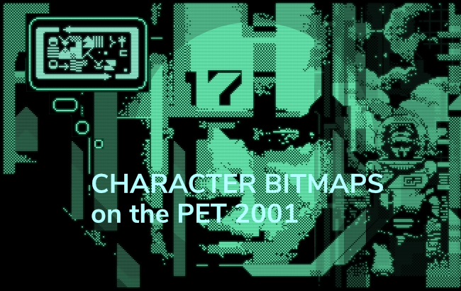
In 2022, Genesis Project (that is: Elder0010 and LRNZ) released a very impressive demo for the Commodore PET 2001 (the original machine and the upgraded PET 2001-N), “A Bright Shining Star”. Among a few other experiments, it showed high-res graphics (in animation) and static bitmap graphics in a vertical strip spanning over 10 characters or 80 pixels.
As readers of this blog may be aware of already, this is particularly impressive, because the graphics of the PET 2001 are strictly character-based, rendering hard-coded character shapes from ROM, and, most importantly, there is no bitmap plane, nor anything resembling sprites.
Run the demo in in-browser emulation on a PET 2001:
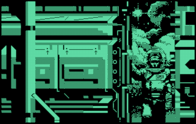
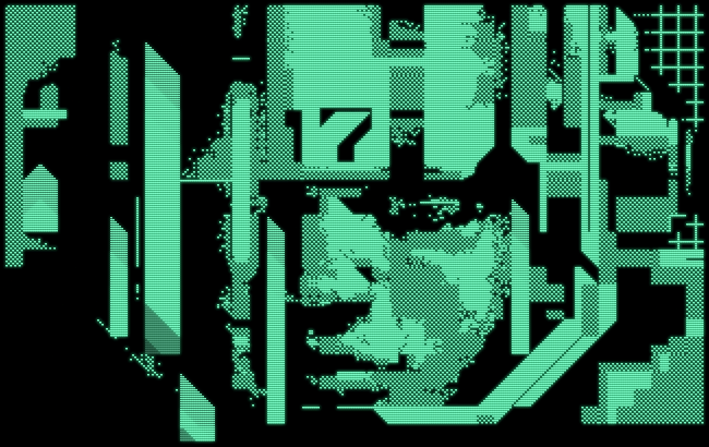
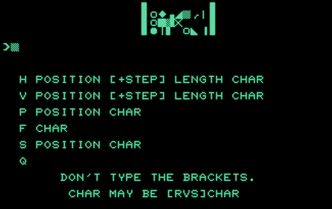
Here are a few stills from the demo:

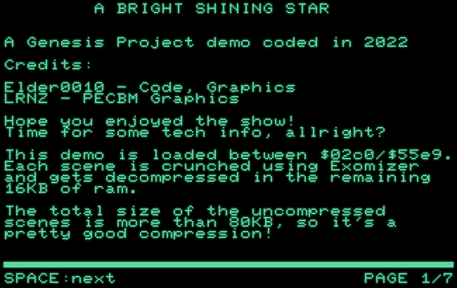
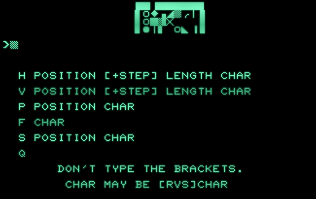
Genesis Project dubbed this display mode “PECBM Graphics” for “PET Extended Char BitMap”. Here is how Elder0010 described it in the accompanying note:
A BRIGHT SHINING STAR
A Genesis Project demo coded in 2022
Credits:
Elder0010 - Code, Graphics
LRNZ - PECBM Graphics
Hope you enjoyed the show!
Time for some tech info, allright?
This demo is loaded between $02c0/$55e9. Each scene is crunched using Exomizer and gets decompressed in the remaining 16KB of ram.
The total size of the uncompressed scenes is more than 80KB, so it's a pretty good compression!
The main goal of this project is to overcome the 8px blockiness of the PET.
Some info about the PET limitations:
- single screen buffer
- non redefinable ROM charset
- no raster interrupts
- no CRTC! (as on 40xx and 80 models)
- no sound (at least in the stock 2001)
- 32KB ram (best case - required for us)I tried to exploit the CRT monitor as much as possible for the effects. For example, a sort of smooth scroll feeling has been obtained in the intro and in the space invaders scene.
Since the tube phosphors have a slow decay time, moving things very fast (8px / frame) fools the eye enough.
PECBM details:
The new video mode is able to display mixed PET and hi-res graphics. The trick is to rewrite the character pointers every rasterline. The length of each line is 64 cycles, therefore you can rewrite up to 10 characters using an unrolled loop, leading to an 80px wide area for the hi-res graphics.
Other characters of the same char-line can be used for standard PETSCII gfx. The character ROM has been analyzed to find all the usable pixels combinations for each 0/7th line of each character. Keep in mind that each 0/7th line can be chosen between each 0/7th line of any character.
In short: since the character line counter loops from 0 to 7, if you are for example at line 2, you can choose to display any line 2 of any character.
Considering that the whole charset is available also in reverted mode, there are enough choices available to display complex hi-res graphics.
PECBM has been used in the door scene, as well as in the astronaut face scene, in the accept no limits slogan and in credits scenes.
The last two mentioned scenes show that PECBM animations are possible, even though some compromises must be done.
The PECBM full screen graphics have been created using a PETSCII editor in conjunction with a custom PECBM editor available at:
www.elder0010.com/uploads/PECBM
I'm too old for this Javascript stuff, so a thousand thanks are flying to Raffaele Rasini for coding the PECBM editor following my specs just in time to let us release at the compo!
The PECBM editor uses the Levenshtein Distance algorithm to convert a stock 80x200 1bit image to PECBM format.
Allright! Enough for this time.
This is Elder0010 signing off.
PET 2001 Graphics — Theory of Operation
Just to point out how impressive this is, we have to consider what’s provided by the PET 2001 to play with: There are only character graphics, based on a fixed character generator in ROM, there is no video chip (CRTC), no registers to fiddle with to dupe the hardware, no raster interrupt — nothing. The video logic is just a shift register and a few TTL chips, like latches and counters. That’s it.
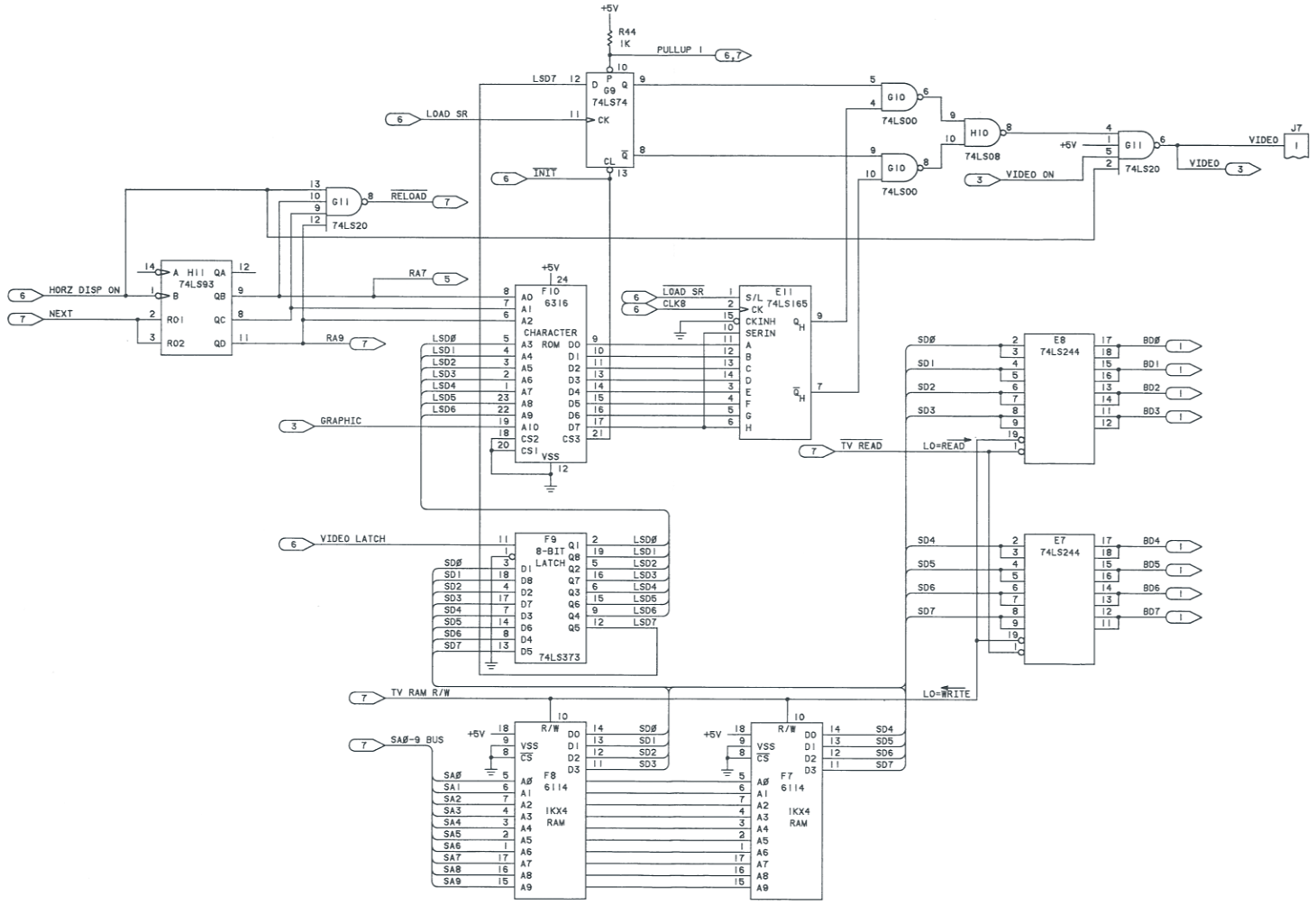
Open in a separate window.
All there is, is 1K of static video RAM mapped at 0x8000 into the address space of the 6502 CPU, worth 25 rows × 40 columns of character codes. A simple counter selects any of the 8 lines for a row from the related bit-map data in the character ROM for each of those characters. Only the lower 7 bits of a character code is for selecting data, while bit #7 (the sign-bit) selects reverse video rendering (there are no reverse video shapes in the character ROM).
There is no line buffer or anything resembling it, just a simple 8-bit latch holding the current character code. (Mantra: “RAM is expensive, TTL is cheap.”) The bit-pattern retrieved from the character ROM is fed into a serial shift register, from where it is read out bit-by-bit (or rather, pixel-by-pixel) and mixed according to the state of the reverse/sign-bit.
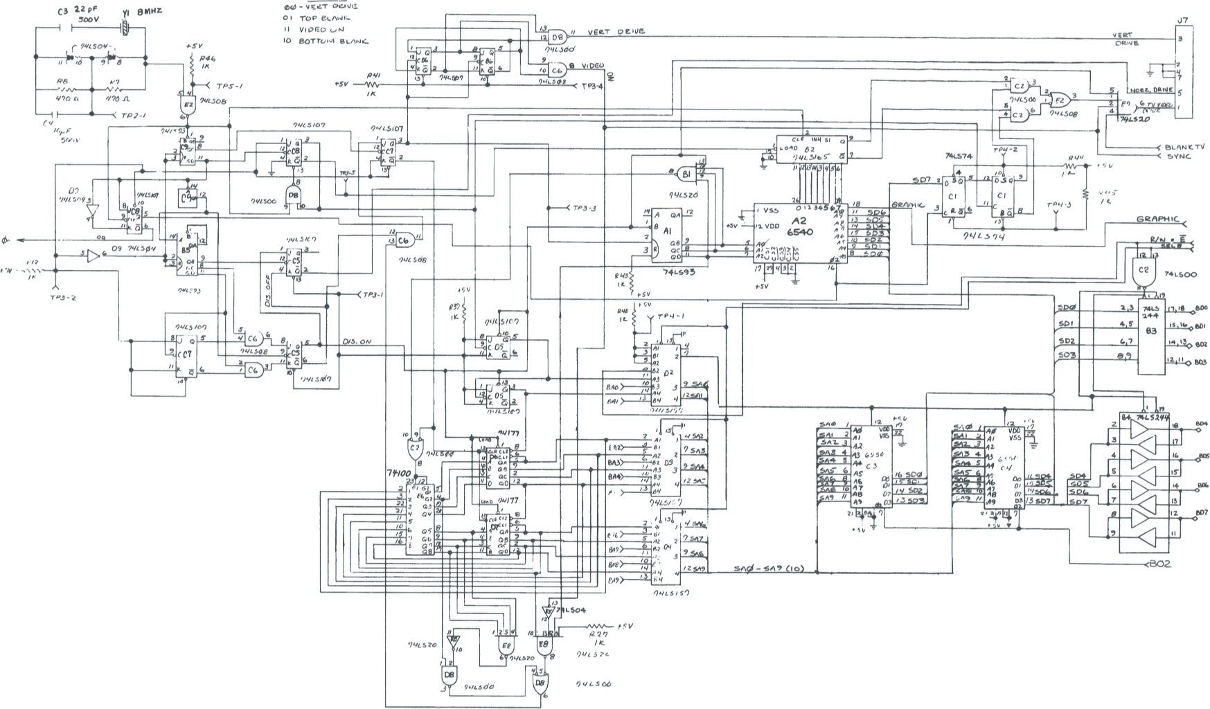
Open in a separate window.
While maybe less clear, we may discern that the system features the following basic, CRT-related states:
00 … NO VERT DRIVE
01 … TOP BLANK
11 … VIDEO ON
10 … BOTTOM BLANK
What matters for character generation and the CPU side of things is the binary “VIDEO ON” signal.
The entire assembly is driven by simple counters, which sync the duty cycle for a video frame to the CPU clock for a slightly modified NTSC frequency of 60.1 fields per second.
Video Timing
The important part for our investigation is really what this means in terms of display timing on the CPU side.
There are 8 scan-lines per row of characters and each line is drawn onto the screen in exactly 64 CPU cycles, 40 for the visible character positions (columns) and 24 for the horizontal blank / retrace interval.
8 lines per character row @ 64 CPU cycles:


0              VISIBLE TEXT             40         H-BLANK        64

     40 character columns @ 8 pixels        retrace, video porch

|<-------------------------------------->|<---------------------->|
               40 CPU cycles                   24 CPU cycles
There’s some beauty to the simplicty of this:
- The duty cycle starts when the video logic goes into V-BLANK for the vrtical retrace interval, which triggers the system interrupt.
- 3,840 CPU cycles later, the video logic comes out of V-BLANK and VIDEO ON comes high.
- It’s only at cycle 3,863, 23 CPU cycles later, that the video logic starts to draw the visible portion of the 1st line of the 1st character in the very 1st row (= row #0, col #0, line #0).
- Now 25 × 8 = 200 lines of video are drawn at 64 cycles, each, for a total of 200 × 64 = 12,800 cycles of screen rendering.
Mind that the scan-line kernel is really 12,800 cycles starting at 3,840 with the preliminaries for the first scan-line, which will start drawing at 3,863. - At cycle #16,640 (3,840 + 12,800 = 16,640) the duty cycle ends and the video logic goes into V-BLANK again, triggering the next system interrupt.
cycle

  0  ---- V-BLANK IRQ
  .
  .
  .
 3840 --- VIDEO ON
  .
 3863 --- (VIDEO ON + 23) 1st line of 1st char, row #0
  .
  .
 +40  --- col 40, H-BLANK
  .
 +64  --- next line (#1 of 0..7), row #0, col #0
  .
  .
  .
  .
 +512 --- row #1, 1st line
  .
  .
  .
  .
  .
  .
  .
  .
16640 --- end of frame → V-BLANK
Notably, this all happens independently of any CPU activity: the video circuitry happily churns along on its own — and the only thing “known” from this on the CPU side of things is the system interrupt as the video logic goes into V-BLANK.
There is also a flag in 0xE840, bit #5 (Port B register of the VIA), fed by the VIDEO ON signal, which is low, whenever the video logic is in V-BLANK. This is for the benefit of the BASIC PRINT command: Since the SRAM used for video memory is rather slow, there’s not enough separation between a CPU access of the video RAM and its access by the video logic. As any such interference will result in “snow” on the secreen, the PRINT command does its job only while this flag is low. (This is, on the original PET 2001 with BASIC versions before version 4.0, which arrived when there were already improved versions of the PET available, utilizing dynamic video RAM, fast enough to cope with simultaneous CPU access.)
Anyhow, it may be observed that there’s nothing in this preventing us (on the program side of things) from changing the contents of a video row in RAM while the video logic is rendering this row, as these are two entirely independent systems. All it needs, is to somehow catch cycle #3863, where the first line of the first character is drawn, and then do our magic for exactly 64 CPU cycles per scan-line.
Of course, this will be restricted to what’s available in the character ROM data for the respective video line, since this is all, we have to work with. But, while not all off the possible 256 (as in 8-bit) pixel combinations will be available, not even the same ones for any of the respective 8 lines, this allows for some fresh creativity.
So, what are these 64 CPU cycles per video line worth?
Well, we can’t do much better than the following, to set any screen character:
LDA #<screen-code>  ;(2) load a screen code value
STA $8xxx           ;(4) store it at the respective location in video RAM
On the 6502, any load immediate instruction is 2 CPU cycles and any store instruction in absolute address mode is another 4 cycles, for a total of 6 CPU cycles per character. So, we may fit 10 character changes into each line (of 64 cycles) with 4 cycles to burn (e.g., two NOP instructions.)
Hi-Res — As of 1980
Impressive as “A Bright Shining Star” is, this was not the first time, the concept was explored. While Genesis Project was probably not aware of this, there is prior art for this: 42 years earlier, in Cursor magazine #18, March 1980, Glen Fisher and Dave Dixon published their “Hi-Res” demo program for the PET 2001.
“Hi-Res” not only draws a character bitmap into a grid of 9 × 5 characters, it also implements a tiny graphics command language in BASIC, which allows users to change the contents of what is drawn on-the-fly (by modifying the operands of the load instructions in the machine language part of the program.)
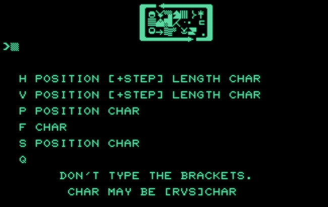
Run the program in in-browser emulation on a PET 2001:
The program as provided on the tape accompanying Cursor #18:
- Download cursor18-hires.prg
BASIC source code with commented ML disassembly (by me, N.L.):
- Download cursor18-hires.txt
This is even more impressive, considering that all that was available at the time, in order to come up with this, was pencil and graph paper and looking up character glyphs and respective screen codes in the manual!
Here is what Fisher & Dixon had to say about this in Cursor #18:
HI-RES... With HI-RES, you can control individual dots on the screen in a 9 character by 5 character area. As you are probably aware, you can write a program that changes the characters on the screen fast enough that your eye sees them both at the same time. HI-RES works in similar way, except that it changes the characters faster than the Pet can redraw the screen. In other words, while the Pet is drawing one line of character dots, HI-RES is changing the characters in the screen memory to a different set, so that the next line of dots come from entirely different characters.
Thus, each line of dots within a character square can come from a different character. The way HI-RES works also forces a limitation on what you can draw with it: you can't put up a line of dots that doesn't come from some existing Pet character. Also, the screen redrawing is fast enough that HIRES can only work on an area 9 characters wide by 5 character high. (One line of dots is displayed in a little less than the time HI-RES can change 10 characters. That is why a limit of 9 characters: the tenth would be progressively chopped short. Also, after 5 rows of characters, the ninth character is being eaten into, so the HI-RES display can only be 5 row high.) Those of you with old Pets will see a lot of 'hash' on your screen, due to the great speed with with HI-RES is changing screen memory (just like when you POKE the screen a lot). The new Pets are built so that changing screen memory doesn't make the 'hash'.
There is more on how the graphics commands work, but we’re here more interested in the actual rendering. For further instructions, please refer to “Cursor #18” (PDF document, tierceron.com).
Here, we’re going to investigate the machine language part of the program, the part, which achieves the actual rendering. The BASIC program which controls this is interesting in itself, not to the least for implementing a tiny graphics language and POKE-ing the resulting screen codes into the respective operands of the machine language program. Moreover, it has to come by without any access to printing to the screen in any way, like by the usual BASIC commands (PRINT, INPUT), since — as we will see — the program spends the entire V-BLANK interval in the machine language routine. So VIDEO ON will be always high, whenever BASIC is executed, locking it effectively out of screen access.
However, this is not what we’re interested here and a closer inspection of this part is left to the reader. We may ignore this entirely, as the program comes with a hi-res graphic already prepared in the machine language part as this is initially loaded, which is also what we’re going to explore here.
HI-RES, the Program
The machine language part is essentially an interrupt service routine, which hooks into the user IRQ vector, which may be used to highjack the system interrupt. As there are two system memory layouts for the PET 2001, one for the “Old ROM” (BASIC 1.0) and one for the ”New ROM” (BASIC 2.0 – 4.0), consequently, there are also two setup routines for this at the very top of the machine language program:
addr  code               disassembly  comments

                         * = $0EF4

0EF4  78                 SEI         ;SYS 3828: setup for BASIC 1.0
0EF5  AD 19 02           LDA $0219   ;swap $0219/$021A (USR-IRQ vector)
0EF8  AE 63 17           LDX $1763   ;and $1763/$1764
0EFB  8D 63 17           STA $1763
0EFE  8E 19 02           STX $0219
0F01  AD 1A 02           LDA $021A
0F04  AE 64 17           LDX $1764
0F07  8D 64 17           STA $1764
0F0A  8E 1A 02           STX $021A
0F0D  58                 CLI
0F0E  60                 RTS

0F0F  78                 SEI         ;SYS 3855: setup for BASIC 2.0-4.0
0F10  AD 90 00           LDA $0090   ;swap $90/$91 (USR-IRQ vector)
0F13  AE 63 17           LDX $1763   ;and $1763/$1764
0F16  8D 63 17           STA $1763
0F19  8E 90 00           STX $0090
0F1C  AD 91 00           LDA $0091
0F1F  AE 64 17           LDX $1764
0F22  8D 64 17           STA $1764
0F25  8E 91 00           STX $0091
0F28  58                 CLI
0F29  60                 RTS
This is actually a rather elegant way to this: At the very end of the program, there is a JMP instruction to the entry point of this custom interrupt routine, and the initialization simply swaps this address and what ever is currently in the interrupt vector. Not only is the interrupt routine installed this way, as this will eventually exit, we will automatically continue with what is probably the system interrupt routine. Here’s this jump instruction as initially loaded and before the target address is swapped:
1762  4C 2A 0F           JMP $0F2A   ;address of the custom IRQ routine
                                     ;will be swapped with contents of USR-IRQ vector
                                     ;(i.e., continue with system interrupt)
This IRQ routine is what follows immediately next — and this also oocupies the entire rest of the program. This is, where the “magic” is done. It is essentially a video kernel, not unlike what is often found in games for the Atari VCS, where this kind of cycle accurate programming is known as “racing the beam”. But here, we’ll not only have to race the beam, we’ll also have to catch up with it, to begin with. (As cycle counts matter, the count for each instruction will be provided in prarntheses.)
The routine starts rather conventionally, by backing up the registers of the 6502 CPU, followed by a few NOPs to adjust the timing:
0F2A  08         i0F2A   PHP         ;(3) interrupt routine (video kernel)
0F2B  48                 PHA         ;(3) back up registers...
0F2C  8A                 TXA         ;(2)
0F2D  48                 PHA         ;(3)
0F2E  98                 TYA         ;(2)
0F2F  48                 PHA         ;(3)
0F30  EA                 NOP         ;(2)
0F31  EA                 NOP         ;(2)
0F32  EA                 NOP         ;(2)
0F33  EA                 NOP         ;(2)
0F34  EA                 NOP         ;(2) 26 cycles
Then, we start to set up the very first row and scan-line of video. Our display will be at columns 17–25 of the first 5 rows of the screen, with the video RAM starting at 0x8000.
0F35  A2 20              LDX #$20    ;(2) write blanks ($20) to cols 17-25, row #0
0F37  A0 20              LDY #$20    ;(2)
0F39  A9 20              LDA #$20    ;(2)
0F3B  8E 11 80           STX $8011   ;(4)
0F3E  8C 12 80           STY $8012   ;(4)
0F41  8D 13 80           STA $8013   ;(4)
0F44  A9 20              LDA #$20    ;(2)
0F46  8D 14 80           STA $8014   ;(4)
0F49  A9 20              LDA #$20    ;(2)
0F4B  8D 15 80           STA $8015   ;(4)
0F4E  A9 20              LDA #$20    ;(2)
0F50  8D 16 80           STA $8016   ;(4)
0F53  A9 20              LDA #$20    ;(2)
0F55  8D 17 80           STA $8017   ;(4)
0F58  A9 20              LDA #$20    ;(2)
0F5A  8D 18 80           STA $8018   ;(4)
0F5D  A9 20              LDA #$20    ;(2)
0F5F  8D 19 80           STA $8019   ;(4)
0F62  A9 00              LDA #$00    ;(2) write 0 to $031A
0F64  8D 1A 03           STA $031A   ;(4)
There are 10 pairs of load immediate and store absolute instructions, each pair 6 CPU cycles, for a total of 60 cycles.
We may observe that that this quite an expensive way to write the same value to 10 memory locations, but keep in mind that this is only the demo data and that the BASIC routine may insert other values, individual to each of the columns. So this is actually required.
Moreover, we may observe that there are 10 pairs of read-store instructions, while we’re serving a display of just 9 columns. This 10th extra pair is (a) for burning cycles (which could be done in other ways, as well) and (b) for the benefit of the BASIC program and the syntax of its tiny graphics language (which provides a simple index into the grid by multiplying rows by 10), which will actually write to this 10th load instruction. (BTW, 0x031A is a location in the cassette buffer, where this write doesn’t matter.)
This is a pattern, which we will find repeated for any of the various rows of video and their scan-lines.
Next comes a loop to burn cycles until the video logic reaches the first scan-line, so that we can commence with rewriting this first row for the second scan-line:
0F67  A0 DD              LDY #$DD    ;(2) now at 62+26 = 88 cycles
0F69  EA         i0F69   NOP         ;(2) wait 221 * 17 - 1 = 3756 cycles
0F6A  EA                 NOP         ;(2)   visible video frame starts
0F6B  EA                 NOP         ;(2)   at cycle 3863 after VBLANK
0F6C  EA                 NOP         ;(2)
0F6D  EA                 NOP         ;(2)
0F6E  EA                 NOP         ;(2)
0F6F  88                 DEY         ;(2)
0F70  D0 F7              BNE i0F69   ;(2/3)
The loop consist of 6 NOP intructions and a DEY instruction, 2 CPU cycles, each, and another BNE instruction for 3 cycles for any branch taken and 2 for the last iteration, where we fall through, for a total of 221 (0xDD) × 17 − 1 = 3756 cycles.
Let’s consider where we are now in the video duty cycle: if we sum this up with the 88 cycles from the start of the routine up to the start of the loop, we’re now at cycle 88 + 3756 = 3844 into the interrupt routine. However, this is not everything, as we have also to consider what happened as the IRQ signal was triggered.
First, there’s the system interrupt routine, which is called via the hard-coded IRQ vector in ROM (at 0xFFFE/0xFFFF), in the case of BASIC 2.0 pointing to 0xE61B:
E61B  48                 PHA           ;(3) backup registers (A, X, Y)
E61C  8A                 TXA           ;(2)
E61D  48                 PHA           ;(3)
E61E  98                 TYA           ;(2)
E61F  48                 PHA           ;(3)
E620  BA                 TSX           ;(2) get status register from stack
E621  BD 04 01           LDA $0104,X   ;(4)
E624  29 10              AND #$10      ;(2) check for break flag
E626  F0 03              BEQ iE62B     ;(2/3) was it a hardware interrupt?
E628  6C 92 00           JMP ($0092)   ;(5) no, a software interrupt: break routine
E62B  6C 90 00   iE62B   JMP ($0090)   ;(5) user-modifyable IRQ vector
As we’re taking the branch at 0xE626, these are 31 cycles. Moreover, the processing of the interrupt takes 7 CPU cycles, and there’s an uncertanty of ε, as well, as the interrupt will only happen, when any currently executed instruction has finished. (As instructions on an NMOS 6502 can take up to 7 cycles, this may mean a delay of up to 6 cycles.)
Therefor, we are at 7 (interrupt) + 31 (system interrupt) + 88 + 3756 = cycle #3882 + ε.
Subtracting 3863 from this, gives us 19, the current position drawn on the screen at
line #0 of row #0, col #(19 + ε)
The important part is that this is after the first line of the first column of our grid drawn and not too far after this, well before the second line of the first character is drawn.
In theory, we could start well before this: The actual write access to memory on the 6502 happens for any absolute store instruction at T-phase #3 or the very last of the 4 CPU cycles:
Absolute Addressing (4 cycles)

Tn    Address Bus   Data Bus   R/W       Comments
T0      PC          OP CODE     1      Fetch OP CODE

T1      PC + 1      ADL         1      Fetch low order byte of
                                       Effective Address

T2      PC + 2      ADH         1      Fetch high order byte of
                                       Effective Address

T3      ADH, ADL    Data        0      Write internal register
                                       to memory
(MCS6500 Microcomputer Family Hardware Manual, January 1976, MOS Technology Inc., p. A-6)
Hence, if we want to write to column #17, we could have started doing so while currently at column #15, since, when the value will be actually written, the video logic will be already processing column #18.
But back to our unknown quantity ε:
The delay combined with this uncertainty is probably why the routine manages only to write 9 characters and why “the tenth would be progressively chopped short.” (With the routine interrupting BASIC, this can be anything up to 6 cycles. However, if we would make sure to be only executing NOPs or similar 2-cycle instructions, when the V-BLANK interrupt triggers, we could minimze this to 1.)
Moreover, there is no real reason, why “after 5 rows of characters, the ninth character” should be “being eaten into”: the display logic and the CPU are perfectly synced at 64 pixels/CPU cycles per scan-line. And, indeed, Genesis Project managed to write a vertical 10 character strip over the entire vertical extent of the screen, demonstrating that with accurate time management even more can be achieved than this 9 × 5 character grid.
Anyhow, let’s see how row #0 is updated for the the second video scan-line (line #1):
                                     ;col 17-25, row 0 (line #1)
                                     ;write: 20 20 67 20 20 20 20 20 20
0F72  A2 20              LDX #$20    ;(2)
0F74  A0 20              LDY #$20    ;(2)
0F76  A9 67              LDA #$67    ;(2)
0F78  8E 11 80           STX $8011   ;(4)
0F7B  8C 12 80           STY $8012   ;(4)
0F7E  8D 13 80           STA $8013   ;(4)
0F81  A9 20              LDA #$20    ;(2)
0F83  8D 14 80           STA $8014   ;(4)
0F86  A9 20              LDA #$20    ;(2)
0F88  8D 15 80           STA $8015   ;(4)
0F8B  A9 20              LDA #$20    ;(2)
0F8D  8D 16 80           STA $8016   ;(4)
0F90  A9 20              LDA #$20    ;(2)
0F92  8D 17 80           STA $8017   ;(4)
0F95  A9 20              LDA #$20    ;(2)
0F97  8D 18 80           STA $8018   ;(4)
0F9A  A9 20              LDA #$20    ;(2)
0F9C  8D 19 80           STA $8019   ;(4)
0F9F  A9 00              LDA #$00    ;(2) write 0 to $031A (dummy write)
0FA1  8D 1A 03           STA $031A   ;(4)
0FA4  EA                 NOP         ;(2)
0FA5  EA                 NOP         ;(2) = 64 cycles per video line
This took exactly 64 cycles, and the two NOPs at the end provide some of a timing buffer — which is actually required, because the write will happen only at the very last cycle of the last store instruction.
The following is more of the same, rinse-and-repeat. One such block for each scan-line of video, 5 × 8 = 40 in total. Here is how line #0 of row #1 is written:
                                     ;col 17-25, row 1 (line #0)
                                     ;write: F6 51 56 66 5A 66 4A 2A F5
10DE  A2 F6              LDX #$F6
10E0  A0 51              LDY #$51
10E2  A9 56              LDA #$56
10E4  8E 39 80           STX $8039
10E7  8C 3A 80           STY $803A
10EA  8D 3B 80           STA $803B
10ED  A9 66              LDA #$66
10EF  8D 3C 80           STA $803C
10F2  A9 5A              LDA #$5A
10F4  8D 3D 80           STA $803D
10F7  A9 66              LDA #$66
10F9  8D 3E 80           STA $803E
10FC  A9 4A              LDA #$4A
10FE  8D 3F 80           STA $803F
1101  A9 2A              LDA #$2A
1103  8D 40 80           STA $8040
1106  A9 F5              LDA #$F5
1108  8D 41 80           STA $8041
110B  A9 20              LDA #$20    ;write $20 to $0342 (dummy write)
110D  8D 42 03           STA $0342
1110  EA                 NOP
1111  EA                 NOP
Eventually, we reach the very last scan-line, as in:
                                     ;col 17-25, row 4 (line #7)
                                     ;write: 20 20 20 20 20 20 20 20 20
172A  A2 20              LDX #$20
172C  A0 20              LDY #$20
172E  A9 20              LDA #$20
1730  8E B1 80           STX $80B1
1733  8C B2 80           STY $80B2
1736  8D B3 80           STA $80B3
1739  A9 20              LDA #$20
173B  8D B4 80           STA $80B4
173E  A9 20              LDA #$20
1740  8D B5 80           STA $80B5
1743  A9 20              LDA #$20
1745  8D B6 80           STA $80B6
1748  A9 20              LDA #$20
174A  8D B7 80           STA $80B7
174D  A9 20              LDA #$20
174F  8D B8 80           STA $80B8
1752  A9 20              LDA #$20
1754  8D B9 80           STA $80B9
1757  A9 20              LDA #$20    ;write $20 to $03BA (dummy write)
1759  8D BA 03           STA $03BA
175C  68                 PLA         ;restore registers
175D  A8                 TAY
175E  68                 PLA
175F  AA                 TAX
1760  68                 PLA
1761  28                 PLP
1762  4C 2A 0F           JMP $0F2A   ;(swapped) continue with system interrupt
1765  00                 BRK

                         .end
With the display kernel finished, there is no further need to sync with the display scan, and there’s no need for the two terminating NOPs. Hence, we immediatly proceed to finish the IRQ routine by restoring the registers as backed up on the stack and jump to the system interrupt.
The final instruction is more a terminating zero-byte, maybe a left-over from testing, doing nothing.
Actually, the inital backup and this restore operation are kind of superfluous, as well, as this is already done by the system interrupt routine, which brought us here in the first place. But it it doesn’t hurt either.
For the full, commented listing, see here: cursor18-hires.txt.
Composing Bitmaps from Character ROM Data
Let’s have a look at the values written by this routine in its default/demo state:
• row #0

line #0:  20 20 20 20 20 20 20 20 20
line #1:  20 20 67 20 20 20 20 20 20
line #2:  E5 A0 76 A0 A0 A0 A0 A0 E7
line #3:  A0 A0 F5 A0 A0 A0 A0 A0 A0
line #4:  A0 A0 76 A0 A0 A0 A0 A0 A0
line #5:  EA 20 67 20 20 20 20 20 F4
line #6:  F6 20 20 20 20 20 20 20 F5
line #7:  F6 20 20 20 20 20 20 20 F5


• row #1

line #0:  F6 51 56 66 5A 66 4A 2A F5
line #1:  F6 51 56 66 5A E6 4A 2A F5
line #2:  F6 51 56 66 5A 66 4A 2A F5
line #3:  F6 51 56 66 5A E6 4A 2A F5
line #4:  F6 57 5A 6C E9 66 55 5D F5
line #5:  F6 57 5A 6C E9 E6 55 5D F5
line #6:  F6 57 5A 6C E9 66 55 5D F5
line #7:  F6 57 5A 6C E9 E6 55 5D F5


• row #2

line #0:  F6 A0 58 A0 4E 20 20 20 F5
line #1:  F6 20 58 A0 4E 20 20 20 F5
line #2:  F6 A0 58 A0 4E 20 20 F5 F5
line #3:  F6 20 58 A0 4E 5D 74 42 F5
line #4:  F6 A0 A0 DC 56 20 74 42 F5
line #5:  F6 20 A0 DC 56 20 20 F5 F5
line #6:  F6 A0 A0 DC 56 20 20 20 F5
line #7:  F6 57 A0 DC 56 20 20 20 F5

• row #3

line #0:  F6 57 20 20 20 20 20 20 F5
line #1:  F6 57 20 61 5C 56 5F 20 F5
line #2:  F6 57 20 E1 5C 56 5F 20 F5
line #3:  F6 57 5D 61 5C 56 5F 20 F5
line #4:  F6 57 48 E1 5C 56 5F 20 F5
line #5:  F6 51 E7 61 20 57 DF 20 F5
line #6:  F6 51 48 E1 20 57 DF 20 F5
line #7:  F6 51 5D 61 20 57 DF 6A F5


• row #4

line #0:  F6 51 20 E1 20 57 DF 6A F5
line #1:  F6 20 20 20 20 20 20 20 F5
line #2:  EA 20 20 20 20 20 65 20 F4
line #3:  A0 A0 A0 A0 A0 A0 75 A0 A0
line #4:  A0 A0 A0 A0 A0 A0 F6 A0 A0
line #5:  E5 A0 A0 A0 A0 A0 75 A0 E7
line #6:  20 20 20 20 20 20 65 20 20
line #7:  20 20 20 20 20 20 20 20 20
And here is what this means in terms of characters and pixels drawn:
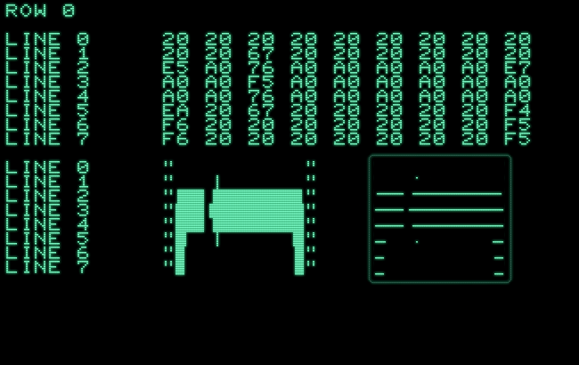
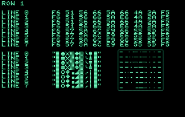
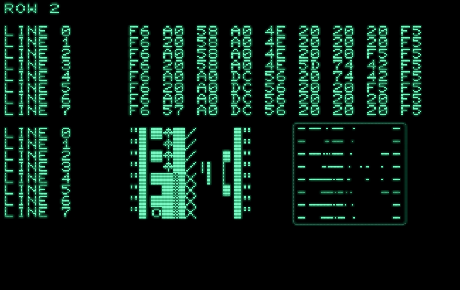
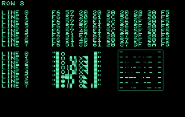
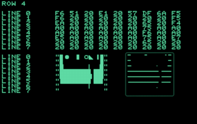
Resulting in the final high-res grid:
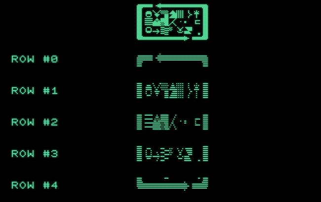
Finally, here are two captures of what the video RAM actually contains at two instances, while displaying that graphic:
Beyond the Character Grid
Pleasing as the result may be, the routine suffers from its all-round capabilities, from its very character as a general purpose display routine. Meaning, if we already know what we’re going to draw, we should be able to exceed this.
First of all, we could store frequently used screen codes, like 0x20 for a blank (a row of 8 unset pixels) and its inverse 0xA0 (a row of 8 set pixels) in X and Y, ahead of the actual display kernel, and use only the accumulator for varying bytes. (E.g., this way, the very first line could be shrunk from 60 cycles to just 40 as in 10 STX instructions. Or, for the subsequent rows, the framing 0xF6 and 0xF5.)
Secondly, if we have a closer look at the pattern drawn, there’s a lot of redundancy:
• row #1

line #0:  F6 51 56 66 5A 66 4A 2A F5
line #1:  F6 51 56 66 5A E6 4A 2A F5
line #2:  F6 51 56 66 5A 66 4A 2A F5
line #3:  F6 51 56 66 5A E6 4A 2A F5
line #4:  F6 57 5A 6C E9 66 55 5D F5
line #5:  F6 57 5A 6C E9 E6 55 5D F5
line #6:  F6 57 5A 6C E9 66 55 5D F5
line #7:  F6 57 5A 6C E9 E6 55 5D F5
As we only need to update screen codes varying between adjacent scan-lines, this is actually just a single one for most of these scan-lines and at a maximum 7 (for line #4).
Thirdly, nothing in this tells us that the patterns must be drawn in adjacent columns (or rows, for the matter). These could be spaced out, as well. As long as we maintain the 64 cycles per scan-line, we’re fine.
Finally, say, in a game, there will be lots of redundancy, as we draw character sprites. And much could be drawn ahead of time, with a display kernel only fixing this up, where needed, but still in a forseeable manner. It may be interesting, if a game like Space Invaders could be drawn like this in high-res. (I believe, there’s a game like this for the Sinclair ZX81, which achieves its graphics in a similar way.)
So there should be some yet unexplored potential to this. All that is required is to treat display logic more like a limited key-value store in a command table than a bit-plane. But keep in mind that will be available only to a limited set of machines, since none of this works on any of the later PETs with the CRTC chip.
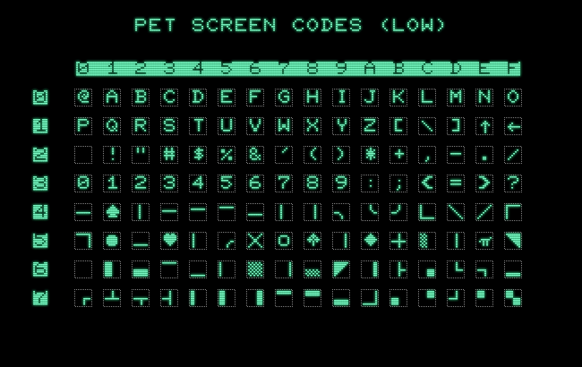
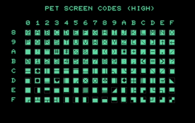
Before you get overly euphoric about this, tough, keep in mind that the following is really all, we have to work with. Especially for line #7, the supply is rather scarce. E.g., we will find it hard to come up with any combination that would result in the shape of the classic Space Invaders sprite in high-res.
(There may be found more in the Lower-Case/Upper-Case set, but, since early PET 2001 will have the lower-case characters in the shifted position and newer PETs the upper-case characters, this isn’t much of a viable option, leaving just the Upper-Case/Graphics set.)
Update: for more see our next post.
— And by this, yes, we are at, “that’s all folks.” —
Norbert Landsteiner,
Vienna, 2025-07-30