Episode 1: Platform Considerations
We are entering late — it's already the 10th of October! — and we now really have to go for it. However, since our humble project may qualify as "extreme retrocomputing," it may be too much to ask for everyone being familiar with the machinery involved, the PDP-1 and Computer Space. So we'll spend the first episode with a closer look at the machines, we're going to port the game from and to.
The DEC PDP-1
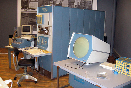
The fully restored DEC PDP-1 at the Computer History Museum, Mountain View, CA.
Photo by Tom Bennett, 2007 (creative commons).
In the November/December 1959 issue of Datamation a single-page article provided a first glimpse of the
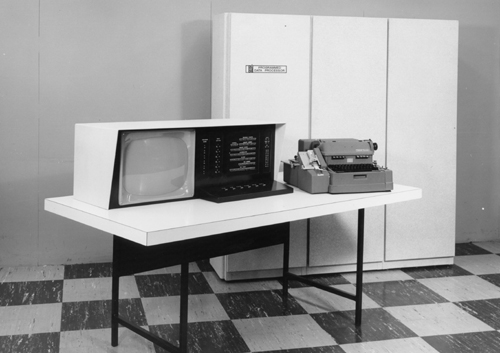
The PDP-1A prototype as depicted in Datamation
(featuring the venerable Flexowriter as a console typewriter).
▶ Have a look at the article: "Special Purpose PDP Has GP Applications" (Datamation, Nov/Dec 1959).
The
(Note: There's a tragic side to every great story, and the story of the PDP-1 is not an exception: In 1963 Ben Guerly was shot at the family table by a former DEC co-worker, leaving behind a family with 5 children. We're going to honor Ben Guerley by having fun with what may be his most important machine.)
Instructing the PDP-1
So what's this marvel of computer engeneering that provided the best of cutting edge technology like transistors and core memory at the price of a better drum computer? (Note: For the purpose of an introduction, we'll restict our description to to what is of most relevance to a programmer.)
Technically, the PDP-1 is a single address, single instruction, stored program computer with a rated cycle speed of 5 MHz, built in solid state technology of modules mostly using Micro-Alloy and Micro-Alloy-Diffused transistors.
Practically, the PDP-1 looks like this:
System block diagram of the DEC PDP-1.
(DEC PDP-1 Manual, F-15B, 1961, p. 7; color added by me, N.L.)
What attributes the realtime capabilities to the PDP-1 is its random acess core memory (random access as opposed sequential access as in delay lines, tanks and tubes of various sorts or drum memory) and its then fast switching time of 5 MHz, mostly owed to the access time of the memory (thus also called a memory cycle). — Previously, RAM had been provided by fragile Williams CRT tubes only and the PDP-1 was one of the first computers to bring random access memory to the masses (relatively that is, about 55 production models PDP-1C and PDP-1D were built in total).
Any of the 4096 18-bit registers of its standard memory may be used either for data or as an instruction. Here, we may have to mention that befor the IBM sytsem/360 popularized octets in computer engeneering, bits came usally in triplets, here 6 triplets making up for the 18-bit word length. Thus, an instruction may be described in 6 octal figures and 4 of them describe the full extent of the 4096 memory locations of its standard address range. As opposed to modern use, DEC manuals number the individual bits starting with 0 at the most significant position (at the left) up to 17 at the least significant position (at the right) — and we'll stick to this convention.
As an instruction, the highest 5 bits encode the op-code, the very 6th bit, the i-bit, provides special functionality, and the lower 12 bits (or 4 octal digits) may either provide a value or a memory address to be used by the instruction. The 5-bits provide a theoretical range of 32 individual instructions, but some of the codes are unused, while other encode entire groups of microcoded instructions.
                      1 1 1 1 1 1 1 1
  0 1 2 3 4 5 6 7 8 9 0 1 2 3 4 5 6 7
┌──────┴───┬─┼─────┴─────┴─────┴─────┐
│  opcode  │i│   address / operand   │     PDP-1 instruction format
└──────────┴─┴───────────────────────┘
There are just two 18-bit registers to be used and accessed by a program, the accumulator (AC) and the in-out register (IO). Further, a few instructions are coupling these two registers into a single 36-bit register. (There are other internal registers, as well, as the program counter, a mememory buffer, registers providing the states of various switches or flags, and so on.) To make things a bit more interesting to a modern programmer, there is no CPU stack and there are no index- or B-registers. Also, there are no condinal jumps, rather condional branches are handled by condional skips of the instruction immediately following in memory. One of them, "isp" (index — i.e., increment — and skip on positive) illustrates the versatility of this instruction set quite well by providing the building block of any simple C-like loop in a single operation.
Moreover, there a 6 programmable flag registers to quickly store states and branch of them as well as 6 sense switches on the console to be controlled by the operator for the same purpose. As another means of human computer interaction an array of 18 console switches represents a test word that can be read by a program.
Any of the operations consumes just a single 5 MHz cycle and an addional one, if a memory access is involved. An interesting feature is the i-bit or "defer bit:" If this bit is set, the contents of this memory location is used for another memory lookup, thus providing universal indirect addressing for any of the memory operations. Most interestingly, this i-bit is more a property of the address than of the instruction, since the process is repeated ad infinitum. (In theory, we might be able to program a state machine just by the use of this deferred addressing.) Practically, this means we may use the address part of any memory location as a pointer with a penalty of 5 MHz in runtime for the extra memory lookup.
As opposed to its later sibling, the popular PDP-8, the deposit of the contents of the accumulator (dac) is non-destructive. There are even two more special deposit instructions, changing either just the address part (dap) or the instruction part (dip) of the targeted memory location. This comes very handy, as PDP-1 programs are notoriously self-manipulating, as there is no stack and we'll have to fix up jump instructions in order to return from a subroutine, or to manipulate a pointer logic provided by the all-mighty i-bit.
Ah, last but not least to mention: The arithmetics of the PDP-1 are one's complement, meaning that the simple bitwise compliment of a value represents the respective negative value. As a side effect there's minus zero, as in 777777 (in octal numbers).
That said, we'll direct any further interest on the subject to the DEC documentation preserved at Bitsavers: www.bitsavers.org/pdf/dec/pdp1/. (Also, we'll cover any details as we'll stumble upon them in the course of our little project.)
What Is it Worth?
So, what does this list of features mean, practically? What is 4K of 18-bit memory worth? Is this ample or rather scarce? Are the 200 MHz cycles (or 100,000 instructions per second) rather slow or fast? We may want answer this by comparing a simple task implemented on the PDP-1 to its respective implementation on another, better known toy computer that came with some amazing visual capabilities for its time at a reasonable price, the popular Apple ][ and its 1 MHz 6502 microprocessor.
As the example we'll subtract two 16-bit values and compare memory sizes and execution time. (We could do this even with 18-bit values using the full extent of the PDP-1's capabilities, but these 2 extra bits would be quite unfair to the 6502.)
Let's compare:
Example 1, PDP-1 (all values octal):
2000   lac 2003      / load contents of loc. 2003 into AC,  2 cycles
2001   sub 2004      / subtract the contents of loc. 2004,  2 cycles
2002   dac 2005      / deposit contents of AC in loc. 2005, 2 cycles
2003   507           / operand 1
2004   412           / operand 2
2005   0             / result
This adds up to 6 addresses in total and 6 CPU cycles at 5 microseconds, to be completed in a total of 30 microseconds.
Example 2, 6502 (all values hex):
$2000   lda $2013    ;3 bytes, 4 cycles
$2003   sec          ;1 byte,  2 cycles
$2004   sbc $2015    ;3 bytes, 4 cycles
$2007   sta $2017    ;3 bytes, 4 cycles
$200A   lda $2014    ;3 bytes, 4 cycles
$200D   sbc $2016    ;3 bytes, 4 cycles
$2010   sta $2018    ;3 bytes, 4 cycles
$2013   $47          ;operand 1 lo-byte
$2014   $01          ;operand 1 hi-byte
$2015   $0A          ;operand 2 lo-byte
$2016   $01          ;operand 2 hi-byte
$2017   $00          ;result lo-byte
$2018   $00          ;result hi-byte
In comparison the 6502 requires 25 memory locations for the same operations and will spend 26 CPU cycles on this, equalling (at a clock speed of 1 MHz) 26 microseconds. (In case we would extend the example to multiplications and divisions, the PDP-1 would be running circles around the 6502, thanks to its high-precision hardware multiply/divide.)
In terms of memory usage, our PDP-1 code usues 108 bits, while the 6502 code uses 200 bits, nearly twice as much. Provided the higher packing potential of any 18-bit data, the 4K of RAM of the PDP-1 is usually compared to 9K of 8-bit memory. Considering that there isn't need for storing a bit-map or any other display data (see below), we may say this is ample for the purpose of a rather simple game. All in all, we may conclude that the PDP-1 should be up to the task of a video game as well as the famous Apple ][.
"Reasonably Priced", You Say?
Previously we mentioned that the PDP-1 came at a reasonable price, comparable to the costs of a drum computer with no memory at all. But, how affordable was this?
A price list by DEC from February 1963 lists a basic system including a CRT at ~ US$ 134,000:
Main unit . . . . . . . . . . . . . . . . . $ 120,000
Display . . . . . . . . . . . . . . . . . . $  14,300
And just for fun:
Additional block 4K memory (Type 12)  . . . $  30,000
Memory controller for Type 12 . . . . . . . $  10,000
Just US$ 134,000 for a small-to-medium mainframe that is manufactured by hand, with the built quality of an airplane? Sounds pretty cheap. But what was this actually worth in early 1960s money?
Prices in the USA, 1960:
Average car . . . . . . . . . . . . . . . . $   2,400
Average home  . . . . . . . . . . . . . . . $  12,000
Oops! — So, this is, uh, 11 newly built family homes and a new car?
Not for you, if you're not a a well-funded institution.
*****
Note: Due to this hefty price, programs implementing solemn, but cheap devices like typewriters and planetarii in software soon earned the ironic prefix "expensive", as in "Expensive Typewriter". We may have wanted to use this for our simulation project, too, but I consider it quite a sacrilege to mess with this honorable tradition. Therefore, we'll opt for "ironic", in stead, emphasizing the role of the PDP-1 and its showcase application Spacewar! as an inspiration for Computer Space.
*****
The Type 30 Visual CRT Display
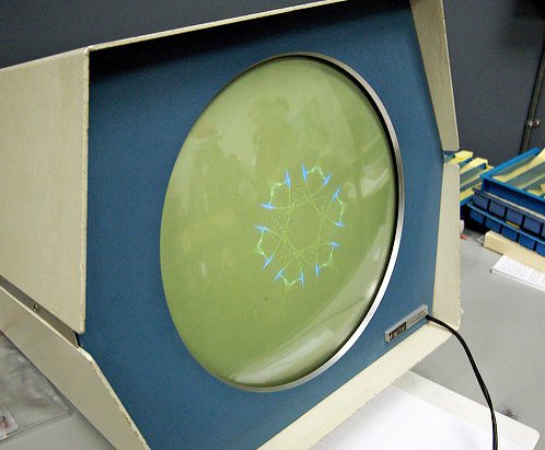
The DEC Type 30 CRT Display (at the CHM, running "Snowflake").
Photo by Marcin Wichary, 2008 (creative commons).
We've still to discuss the display that came with the PDP-1 as an option (about half of the PDP-1s had one) in order to evaluate the PDP-1 as a gaming platform. The Type 30 CRT was first called "Visual CRT Display" — and I like this name as it recalls a time, when a CRT associated to a computer was rather likely to be used as a storing device (compare the Williams tube) than to be used for display purpose. But soon, the Type 30 CRT was known as the "Precision CRT Display", referring to its unusual spot stability of just half a display location.
The Type 30 CRT was a point-plotting display rendering 1024 × 1024 display locations in a 9 ³/8 inches by 9 ³/8 inches square at 8 intensities (or brightnesses) on its circular tube. Some of this may require a bit of an explanation: Like most of the early displays, the Type 30 CRT was a point-plotting display, also known as X/Y display. This is a random access display (as opposed to a raster CRT), just like the better known vector display, but without any memory. All it does is to accept a digitally encoded display location by x- and y-coordinates, direct its electron gun at this very spot and fire its beam for short period of time, just enough to activate the phosphor. All the timing, refreshing and everything with regard to keeping the display image stable and flicker-free is left to the program. (Yet another term for this kind of display was painted or animated display, referring to this shoot-and-forget process of instructing and maintining the display.)
Considering the costs of core memory (the 1963 price list has a 4K module of 18-bit memory at $ 30,000), this was the only way to go: Leaving feasibility, access times, and the required amount of engeneering aside, doing some simple math just on the cores required for a frame buffer of 1024 × 1024 locations at 9 states (8 intensities and unintensified), 9Mbit in total, provides the simple answer: Would this have been feasable at all, the memory would have amounted to US$ 3,840,000 in 1960 money! Random access with as little memory as possible was the only way to go.
But random access comes at a price in engineering, too: As the beam isn't smoothly traveling at a constant speed across the screen, as with raster display scopes, we've to consider the maximum distance between any two points, the diagonal between 1024 × 1024 display locations. In order to travel the distances as quick as possible, high voltages have to be applied (the power supply of the Type 30 display provides +10,000 V to the tube, while the logic works on +10 V and -15 V). But this is causing over- and undershoots and ringing in the deflection coils, which are to be handled by compensation circuits and a cooling phase. Otherwise, two consecutive activations at the same coordinates wouldn't result in the activation of the same spot, resulting in a blurry or even jumpy image. As a result, there's a minimum time between any two display commands issued to the display of 50 microseconds (worth 10 instruction cycles of the
DEC Type 30 CRT display deflection compensation characteristics.
(DEC manual, Precision CRT Display Type 30E, F-15(30E), 1963, p. 3-8)
While the compensation circuits and cooling time make for a high precision image (in fact, the precision was so good that the Type 30 CRT could be used in conjunction with a photomultiplyer to scan plots and data points by simply afixing the printout of a graph on its tube), this establishes the main bottleneck of the PDP-1 as a gaming platform by limiting the number of dots that may populate the screen while keeping an acceptable and stable refresh rate.
Another characteristic of the Type 30 CRT is its tube, or to be precise, the dual P7 phosphor. It's the same type of tube used for scan radar, using one sort of phosphor for a newly activated blip (also the signal registered by the optional light pen) and another one for a persistent sustain. In the case of the Type 30 CRT, the short activation phosphor came at a bright blue color and the long sustain one in a warm, yellowish green. While these blended one into another smoothly in the analog process, distinctive colors are noticeable if digitized by the frame-rate of capturing device, like video or still images (compare the above photo), also posing some challenges for any kind of emulation of the scope. But in natura, this isn't posing much of a problem, and rather helps in stabilizing the image. In Spacewar! the P7 phosphor is responsible for the characteristic trails drawn by any moving objects and enables the program to refresh and update its background starfield (Peter Samson's "Expensive Planetarium") only every second frames, while still being steadily visible thanks to the afterglow.
(A side effect of the dual phosphor is responsible for this skipped frames of Spacewar!'s background stars: The 8 intensities of the display do not scale too well, as the visible brightness is the result of two overlayed phosphor layers. Therefor the fathers of Spacewar! decided to rather modulate the brightnesses by the refresh rate than by using the itensity codes.)
The resolution of the display is that fine, that two adjacent display locations are overlapping in spot sizes. That is, for the average spot size at medium brightness, since spot sizes vary with activation. Therefor we must not speak of pixels*) in this context, but rather confine ourselves to the use of the term "display location". — DEC rated the visual resolution at 512 × 512 dots, half the technical resolution. (For the purpose of emulation, we're not restricted to any specific scale, since our emulation does some nifty subpixel mapping. I've found rendering the display at 640 × 640 px as quite optimal as this provides some detail and still fits most modern screens.)
(Note: Besides the Type 30 CRT, there was also the Ultra-Precision CRT Display Type 31 meant for photo-reproductive purpose, rendering 4096 × 4096 addressable locations at 3 by 3 inches. — Take that, Retina Display!)
*****
*) Nerdy Excursus on the Term Pixel and Picture Space (cum grano salis)
Orignally, the term "pixel", short for "picture element", related to a mosaic-like picture element as described by Athur Korn in his 1904 book Elektrische Fernphotographie, "streng genommen ein kleines Flächenelement" (strictly speaking a small surface element). Opposed to this, a pixel is by modern definition a dimensionless point and any visual and spacial representation already involves some kind of interpolation. To make a difference, we may opt for the alternative term "pel" (also for picture element) which was once popular in video engineering and may be traced back to William F. Schreiber, professor at MIT, who introduced this term in the 1960s as an English equivalent to the German "Bildpunkt" (the definition of which we've already provided above) and its shorthand "BP".
However, in general understanding the term "pixel" still refers to the small surface elements that make up the mosaic of the picture. While strictly speaking any adjacent dots on the surface of the Type 30 CRT, which are still separated in its abstract coordinate system, may be still considered dimensionless pixels, the round, overlapping dots do not qualify as "pels" in a strict sense or "pixels" in a general understanding.
*****
Computer Space
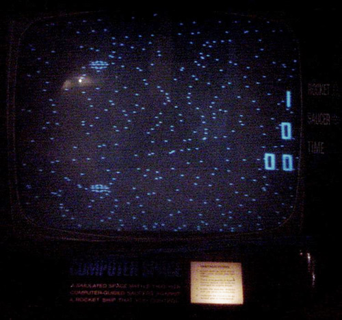
Computer Space (screenshot: www.pinrepair.com/arcade/cspace.htm).
Computer Space, the game we're going to program, is not a program originally but an electronic device.
In 1971, ten years after the conceiving of Spacewar!, computers were still expensive. Too expensive for the purposes of Nolan Bushnell, with the first microprocessors ranging at about US$ 10,000 (now in a bit cheaper 1970s money) and memory, while also a bit more affordable, still in the roofs. At least it was too expensive for the purpose of a coin operating arcade machine that was to earn its construction costs and some surplus while being fed with quarters. The way to go, the path Nolan Bushnell chose to go with the help of Ted Dabney, was solid state electronics, 74xx logic to be precise. What they accomplished was not only the first arcade video game, but also what may have been the first human vs. machine video game. While the the thrills of Spacewar!, which clearly inspired Computer Space, was in the human-to-human interaction through the computer, a personal battle in the virtual realms provided by the machine, Computer Space had to rethink the concept entirely by replacing the human opponent by an agency that was to be controlled by the machine, two flying saucers, vertically stacked at a constant distance ontop each other.
(Note: There had been endeavors to implement a computer controlled UFO in Spacewar!, as Albert W. Kuhfeld recounts of late Spacewar! hacking at MIT in "Spacewar" [Analog Science Fiction Science Fact Magazine, July 1971, pp 67-79]: "The only real program development going on was done by a couple of students trying to introduce a computer-piloted flying saucer to occasionally zoom through the game as a kind of “wild variable.” To the best of my knowledge, they never got it working.")
Still, many of the elements of Spacewar! are still in place: There's still a maneuvering spaceship against the backdrop of stars, there are still photon torpedoes, and while there's no central star, gravity, or hyperspace, there's sound — amazing sound, amazingly crude sound, produced by some analog circuitry! The graphics may be simpler, but they still grasp the essence of space flight fantasy. — And we haven't mentioned yet the futuristic design of the shiny fiberglass cabinet, designed by Nolan Bushnell himself, coming in four colors, yellow, red, blue and green!
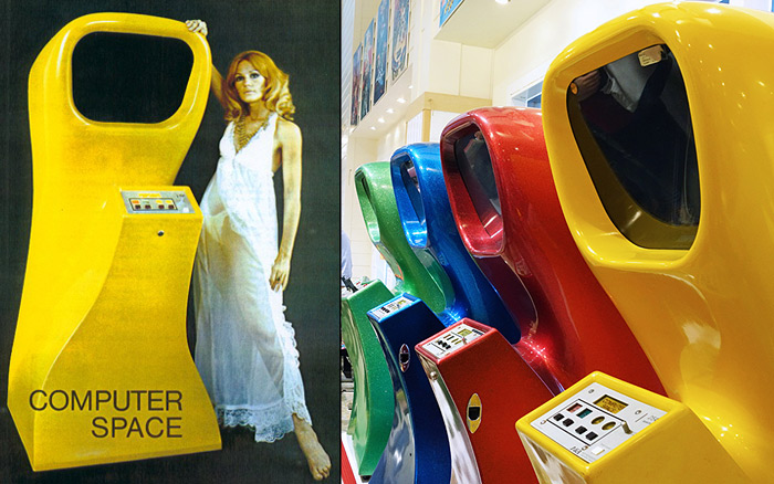
Computer Space cabinet: original flyer art and at an exhibition.
Another addition of Computer Space was a constant on-screen display of the scores (player and saucers respectively) and the play time (counting up to 99). Computer Space was in essence a survival game and its object was to survive against the automaton. If you were good enough, this earned you an etxtra time (Computer Space's version of hyperspace), now displayed in reverse black on white video. Therefor much of the thrill of the game was in competing against the AI, and what a hard game this is! Commercially the game (produced and distributed by Nutting Associates) was only a mild success, and the cabinets soon vanished from the arcades with just a few of the about 1,500 machines surviving. (Personally, my guess is that this was for the difficulty of the gameplay, which was a great success with testing engineers who were already familiar with the concept and became successively hooked by the challenge, but may have been to much of a challenge for the unprepared public to get into the game at the beginning.)
Computer Space gameplay (youtube.com)
Another Computer Space gameplay video (youtube.com)
Technically, the single player version of Computer Space (there's a rather arcane two player version, as well) consist of three logic boards, one of them famously reproducing the outlines of the on-screen items in the layout of diodes, which were hooked up to a vanilla black and white TV set. By then, cost-related considerations had changed quite a bit, with the raster display being the option of choice and CPU-less, even memory-less electronics directly riding the beam of the CRT. (A feature to be reencountered in Atari's as popular as econimical 2600 VCS console.)
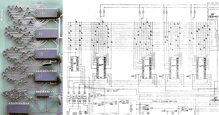
Computer Space bord layout detail: board (image: pinrepair.com) and schematics side by side.
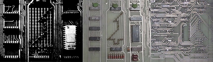
An interesting glimpse into the use of a diode matrix as a cost effective alternative to image ROMs in early video games: Layout of the player's rocket in Atari's "Space Race," 1973: Configurable matrix on an engineering prototype board (left, image: Arkush, William, The Textbook of Video Game Logic, Volume I. Kush N' Stuff, Campbell, CA, 1976; p.90.) and the same section on the final production board (front- and backside; images: ebay.com, edited).
Links / Resources
There a few sites to consider for more information on Computer Space:
- www.computerspacefan.com
- The Computer Space Manual, including schematics (computerspacefan.com)
- A corrected, modern set of Computer Space schematics (github.com)
- Computer Space and the Dawn of the Arcade Game (technologizer.com, 2011)
- 1972 Nutting Associates Computer Space (pinrepair.com)
- Video review of the machine, gameplay towards the end (at 23:00): Computer Space – (Nutting Associates 1971)
- Fixing Computer Space by Ed Fries (2015)
- A series of repair videos by John Jacobsen (John's Arcade Game Reviews & Tech, 2015–2016)
- Finally, there's, of course, a Wikipedia page on Computer Space.
Simulators
- In software, there's a Computer Space Simulator by Mike "Moose" O'Malley for Windows (2005, hosted at computerspacefan.com).
- And in modern hardware, there's a FPGA implementation of Computer Space (rendering in NTSC/PAL), also see this thread and this video.
Implementing the Game
Here are some observations on Computer Space, accompanied by considerations regarding the PDP-1 as the target platform:
- Generally, Spacewar! serves as the proof of concept on the feasibility of the implementation. There are about as many tasks and higher order computations (like square roots or sines/cosines) to be performed, or even slightly less of them. Good news!
- Computer Space features, like Spacewar!, a background starfield. Unlike Spacewar!'s it's a fixed and static one: At any time we see the same constellation of stars. And there are lots of them! Since the runtime required to display a dot on the screen is our major bottleneck, we may consider our own solution.
- There's a rotating and maneuverable spaceship (rocket) representing the player. The graphics are much less smooth than in Spacewar!, meaning we shouldn't face any runtime problems here.
- Unlike with Spacewar!, thrust isn't adding up for the player's spaceship. In stead, the rocket is apperently travelling at a constant speed.
- Instead of a second player's spaceship, there are two additional saucers, controlled by the game AI. Again, the graphics are quite coarse and the runtime required may be even less than for painting a single ship in Spacewar!.
- There's just a single torpedo for the player's spaceship and another one for the saucer on the screen at any time. As a special feature the torpedo fired by the rocket is stearable as it is linked to the rocket's rotational angle. Like in Spacewar! torpedoes have a time fuse and will explode after a certain time.
- Speaking of explosions, there's a graphic explosion effect for the player's ship being hit by a torpedo, but not for a spacship to saucer collision. For the latter, the screen just flashes in reverse video. — We will not be able to implement reverse video on a random access display! Therefor, we're going to display explosion graphics in any case.
- The same applies to the "Hyperspace" extra play. Reverse video is beyond the capabilities of the PDP-1 and the Type 30 CRT. Since the PDP-1 is not a coin operating machine, this effect may be of limited importance anyway.
- All the graphics in Computer Space are quite coarse with clearly distinguishable pixels. Also, there's a vertical off-screen area, from which one of the saucers may fire as from a hidden ambush. I'm guessing the internal representation is a square playfield clipped by the 4:3 letterbox of the NTSC-type TV screen. Also, I'm guessing from the use of 74xx-series logic chips and the discernible pixels that the dimension of this internal representation may be 256 × 256 locations.
- There will be almost certainly not enough resources to imitate this vertical clipping on the PDP-1. Instead, we're going display the full internal square space filling the square rendering area of the Type 30 CRT.
- Another problem regarding graphics poses the much higher resolution of the PDP-1 and the Type 30 CRT as compared to Computer Space: Thanks to the afterglow of the P7 phosphor, any moving object will paint a visible trail, exhibiting any jagged or interrupted movement only too clearly to the observer. Thus we may want to keep any movements as smooth as possible.
- While the graphics of Computer Space may not be as smooth as the ones produced by the PDP-1, Computer Space has sound — amazing sound! — a feature not availbale at the PDP-1. We may consider to add a watchdog to the PDP-1 emulation and hook some sound effects to certain values of the program counter.
- The AI of Computer Space is known to be quite challenging. Based on experiences while programming some early browser games, I'm rather convinced that a simple, random based AI is much deadlier in a small, confined space than a more elaborate one. I'm guessing that this is also the case with Computer Space. We'll see how this may scale with a higher resolution… However, we'll have to perform some higher order computation in order to calculate any trajectories for the soucers' targeting, making up for the missing gravity calculations.
- Computer Space has a constant on-screen display of scores and the elapsed play time (in seconds). There's a single digit for the score, famously displaying scores from 10 to 15 in some gibberish. This is related to the 7448 seven segment decoder chip used to generate the score display that counts up to and around 15, generating lower case letters for any values greater than 9. This values were not meant to be shown on the screen, but due to a common defect some enigmatic patterns were displayed anyway. Certainly, we're going to reproduce this hex display for the scores. While there's an optional high-speed symbol generator for the PDP-1, it was not part of the standard equipment. Thus we'll have to implement the on-screen display entirely in software, probably spending most of the runtime gained from the relatively simpler graphics (as compared to our benchmark game, Spacewar!).
- There's no realtime clock on the PDP-1, thus we'll have to keep time ourselves. Generally, we're going to have as few branches in our main logic as possible, and — profitting from the example of Spacewar! — we'll declare a time budget for each frame and spend any extra cycles left in a count-up loop. Moreover, we're not expecting to run out of memory and will, as a general rule, opt for time as often as possible when facing the time-vs-space paradigm.
- As for player input, we'll stick with the conventions established by Spacewar! (utilizing either the testword switches on the control console or any special "control boxes" attached to one of the taper pin panels at the rear of the PDP-1). As there are two players in Spacewar! and just a single one in Computer Space, we'll map both inputs to single one, so that the game may be played by using either of the player controls.
That's all for our initial post.
Next time, we'll start our project with the implementation of the background stars …
▶ Next: Episode 2: Stars & Sync
▲ Back to the index.
2016-10-10, Vienna, Austria
www.masswerk.at – contact me.
— This series is part of Retrochallenge 2016/10. —