“PET-Globe” Demo
An avidly spinning globe for the Commodore PET — and some bit-vectors.
Well, I made another thing — in #6502 code and #PETSCII.
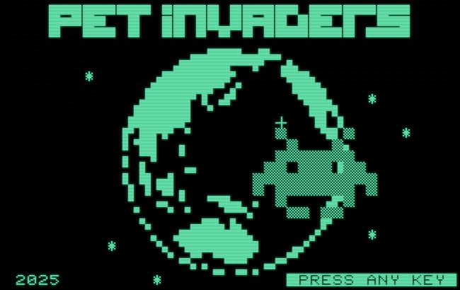
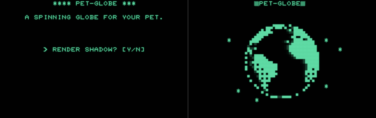
I’ve a new PET game in the works, aptly named “PET Invaders”, since it’s for the Commodore PET and, yes, another Space Invaders-style game. (I told you that there may be some forshadowing involved in the New Year’s post.) The game is all about rendering “fat pixels” in PETSCII quarter-block characters (trading static resolution for higher dynamic resolution) and currently features a splash screen that looks like this:
The versed retrogamer may have spotted it already: this is a tribute, heavily inspired by the intro sequence to the “Space Invader” game for the Sharp MZ-80 (which is restricted to character graphics, as well, similar to PETSCII). And this original inspiration isn’t just static, it features an animation of (I think) twelve static slides. So, can we do something similar for the PET, but even improve on this, by rendering a real animated globe?
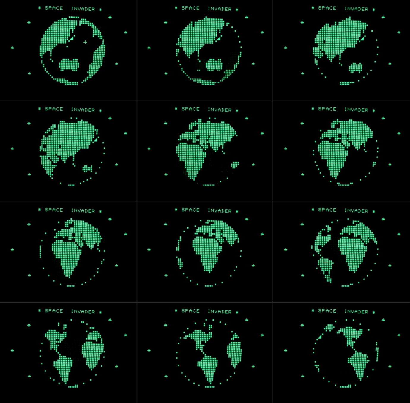
Earth is surrounded by (attacking) alien saucers, which are part of the MZ-80 character set.
Source: YouTube, @Sharp MZ-80A.
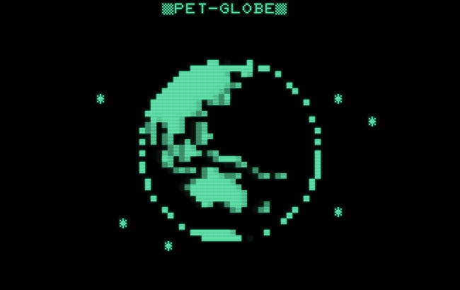
And here’s our little attempt at that global challenge:
I will probably keep the static splash screen for an 8K version of the game and use this for a 16K version.
The rendering area of the animation is a bit smaller than the depiction in the static version, but it runs surprisingly fast and fluidly. (This reduced size is the price, we have to pay, in order to fit everything into 8-bit suitable data structures and to maintain a not too extensive program size.)
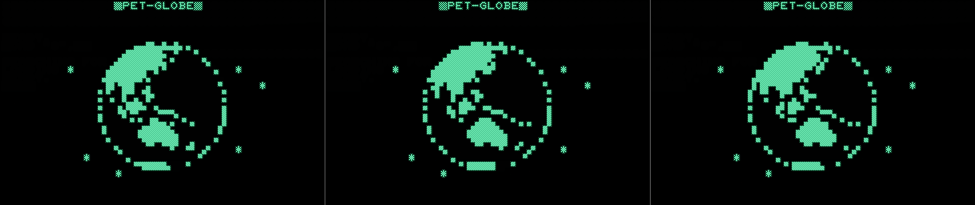
Here’s a short video of the program running, which is now available as a stand-alone demo, and the globe spinning:
Or just click here, for a direct link to run the “PET-Globe” in in-browser emulation:
The “PET-Globe” demo, as a stand-alone program (PRG), is available for download here:
Requirements: any 40-columns PET, any ROM version, 8K of RAM or better.
“PET-Globe” — Making-Of
Obviously, we have to resort to machine language (assembler), since there is no way we could do this in BASIC. The 6502 assembler, I used for this, is my own, the one embedded into the PET 2001 emulator, which allows for rapid development by simply dragging & dropping assembler source files.
The crucial question, though, is the one of data structures and their organization. How do fit the entire world into about 4.8K and how can we access this suitably fast?
Here are the ingredients:
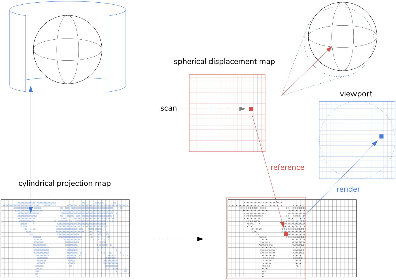
- a world map in cylindrical projection (preprocessed and then hand edited in ASCII format)
- a displacement map for spherical projection
- a mask defining the rendering area, off-pixels and some static pixels indicating the border of the globe. (Further down the road, this may also allow us to leave some areas of the image untouched, like a superimposed Space Invader.)
As we’re going to render this in “fat-pixels”, AKA quarter-block PETSCII characters (▖, ▗, ▘, ▝, and any combinations thereof), we also need to transition from a full resolution of 32 × 32 pixels to a half-size video resolution of 16 × 16 characters.For this we also need:
- a 16 × 16 bytes (256 bytes) scratch area, where we store set pixels as 4-bit (a bit for every fat pixel) bit-vectors and then render them to PETSCII characters using a lookup table.
(As we’ll se later, the 16 × 16 characters size limitation doesn‘t come from the total of 256 bytes, as may be presumed on first sight, but rather from the size of the displacement maps and handy 8-bit displacement offsets, which really limits our pixel resolution to 32 × 32.)
Preparing the Data
The preparation of this data wouldn’t have been possible without modern equipment. Of course, we could have processed our displacement in BASIC and encoded the world map by hand, but assembling this into something runable, so that we can test it, would have been unspeakably tedious with all the intermediate steps required on each iteration.
So I rather built a tiny web page, which first samples and rendered a world map to a suitable size and then exported this as ASCII strings, an easily editable format (and also appropriately old-school), which was used for any further steps. This page was also used to generate and export a static spherical projection map.
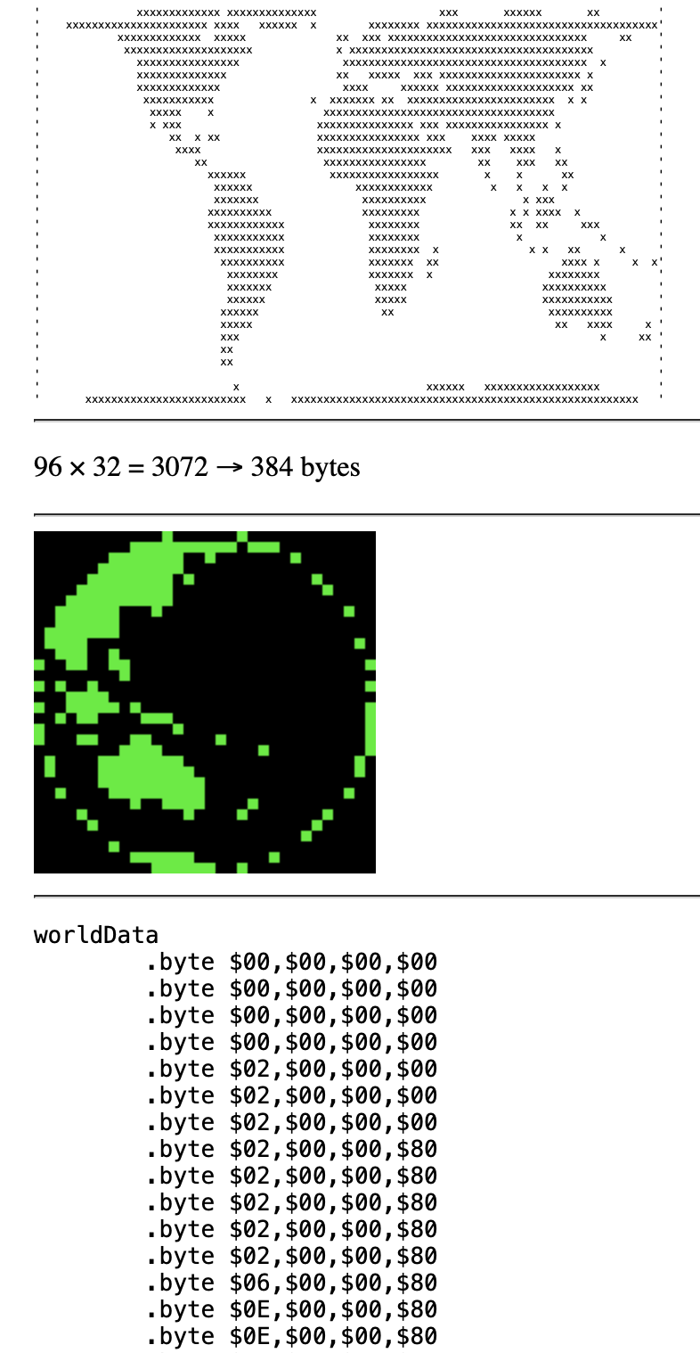
As the individual positions hold just 1-bit data, as in on/off, this can be obviously compressed into 8-bit bit-vectors, resulting in a width of the data stream of just 4 bytes. (4 × 8 = 32)
For this, we’ll rotate the map data by 90°, so that it runs column by column down in rows. This way, we can easily iterate over them per column and (spoilers) it will facilitate animation.
bit-vector   map col #0               map col #1

              ┌─ .  0                  ┌─ .  0
              │  x  1                  │  x  1
              │  .  2                  │  x  2
[-1--1-1-] <──┤  x  3    [11--111-] <──┤  x  3
 76543210     │  .  4     76543210     │  .  4
              │  .  5                  │  .  5
cv0 = 0x4A    │  x  6      = 0xCE      │  x  6
              └─ .  7                  └─ x  7
              ┌─ x  0
              │  x  1                   (...)
              │  x  2
[11--1111] <──┤  x  3
 76543210     │  .  4
              │  .  5
cv1 = 0xC3    │  x  6
              └─ x  7
              ┌─ x  0
              │  x  1                   (...)
              │  .  2
[11-11-11] <──┤  x  3
 76543210     │  x  4
              │  .  5
cv2 = 0xDB    │  x  6
              └─ x  7
              ┌─ x  0
              │  x  1                   (...)
              │  .  2
[----1-11] <──┤  x  3
 76543210     │  .  4
              │  .  5
cv3 = 0x0B    │  .  6
              └─ .  7


worldData
;               cv0  cv1  cv2  cv3  --> columns

          .byte $4A, $C3, $DB, $0B  ; r0   │
          .byte $CE, ...            ; r1   v
                                    ; r2  rows
The displacement map for the spherical projection is a static lookup table, giving a lookup-address relative to the top-left origin of the map data (at the current view state). The beauty of this is that this remains always the same for each animation step, as long if we do not aspire to tilt the rotational axis or our viewing angle.
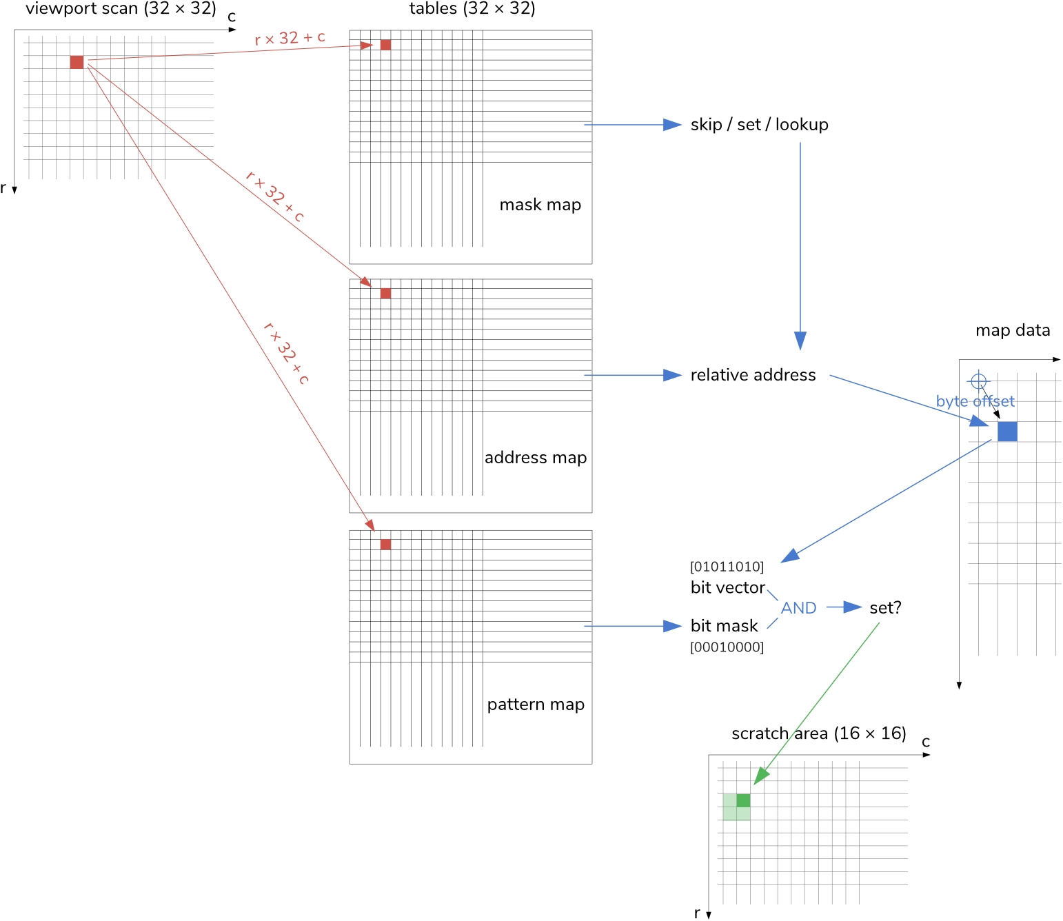
As it happens, the lookup vectors into the map data are for a 32 × 32 viewport up to 11 bits wide. How could we encode this into 8-bits? Well, we do something similar as before, splitting this into an 8-bit byte offset (0…255) and a 3-bit mask (0…7), which should allow us to easily retrieve the respective byte from the map data and then simply AND this with the mask, which represents a bit-vector of the same type. If this gives a non-zero result, we’ll set that pixel, otherwise, we’ll let it unset.
Notably, we won’t store the low part of the displacement vector in binary, rather, we’ll set the nth bit high (1 << n), so that there is a single bit set, everytime, corresponding with how we encoding the map data earlier. In other words, this mask selects a position in/from the bit-vector retrieved from the map data.
— Yes, this is a pre-computed transformer. But certainly not a LLM, more like a (very) small dot displacement model. ;-)
The downside of this is that we actually need two tables, one for the address vector and one for the bit selection mask. At 32 × 32 = 1024 bytes = 1 KB, each, these maps come in quite substantial size for our humble target machine. Also, we’ll need another one, for the view mask, we’ve already mentioned before. That’s 3 KB in auxiliary tables for just 384 bytes (4 × 96) of actual display data!
(This 8-bit byte offset is strikingly ideal for indexed addressing. I would have loved to make this 40 × 40, but this would have resulted in some 12-bit offsets, a total ruin to our 8 + 3 bits lookup scheme.)
Sampling
Anyways, this is how we do it:
Reducing the final rendering dimension to half, a division by 2, is as easy as a logical shift right (LSR).
What we’ll write into this scratch area is yet another bit-vector — but, this time, it’s entirely arbitrary. Hence, we have to come up with a convention for this:
;	bitmap codes for quarter-blocks
;
;	x.
;	..   … 1
;
;	.x
;	..   … 2
;
;	..
;	x.   … 4
;
;	..
;	.x   … 8

screenCodes             ;bitmap codes to screen codes
	.byte $20   ;  0
	.byte $7E   ;  1
	.byte $7C   ;  2
	.byte $E2   ;  3
	.byte $7B   ;  4
	.byte $61   ;  5
	.byte $FF   ;  6
	.byte $EC   ;  7
	.byte $6C   ;  8
	.byte $7F   ;  9
	.byte $E1   ; 10
	.byte $FB   ; 11
	.byte $62   ; 12
	.byte $FC   ; 13
	.byte $FE   ; 14
	.byte $A0   ; 15
We could determine the appropriate code by the value in the carry flag, which holds the least significant bit as it has been shifted out, but we opt for an XOR operation instead (which is actually a bit slower, but conceptionally pleasing).
          column            XOR
row
        even   odd

even     1      2    ...     3

odd      4      8    ...    12
The final operation is then to transform these bitmap codes into PETSCII characters by the use of the above lookup table for PETSCII characters and render this to the screen.
This is what this looks like in 6502 assembler code:
sample
	lda #0                  ;initialize row count
	sta TY                  ;zeropage address
	;(...)                  ;set up some further values…
	lda #1                  ;initialize which bit to render
	sta SCRATCHBIT          ;zeropage address
	lda #3                  :XOR-mask to alternate between states
	sta SCRATCHMASK         ;zeropage address

sampleRow
	ldx #0                  ;X-register holds current column to scan

samplePoint
readMask	lda $ffff,x             ;test MASK
	bmi skip                ;$80: ignore / skip
	asl
	bmi setPixel            ;$40: set uncondionally (border)
readProjA	ldy $ffff,x             ;PROJECTION ADDRESS
readWData	lda worldData,y         ;use it as offset into worldData
readProjB	and $ffff,x             ;PROJECTION BIT-MASK (select)
	beq skip                ;skip, unless active
setPixel	txa
	lsr                     ;halve the resolution
	tay
	lda SCRATCHBIT          ;load and OR pattern for scratch area
	ora (SCRATCHPTR),y      ;indirect indexed reference using a pointer
	sta (SCRATCHPTR),y      ;                          in the zero-page
skip	inx                     ;iterate for next data point
	cpx #32                 ;row done?
	beq nextRow
	lda SCRATCHBIT          ;next data-point, same row
	eor SCRATCHMASK         ;alternate value in SCRATCHBIT
	sta SCRATCHBIT
	jmp samplePoint         ;loop for next column

nextRow	ldy TY                  ;increment row count
	iny
	cpy #32                 ;32 rows done?
	beq sampleDone
	sty TY                  ;prepare for next row

	{set SCRATCHBIT & SCRATCHMASK according to even and odd rows}
	{increment SCRATCHPTR by 16 on even rows}
	{increment MASK by 32}
	{increment PROJECTION ADDRESS by 32}
	{increment PROJECTION BIT-MASK by 32}

	jmp sampleRow           ;loop for next row

sampleDone	rts


Note: “{…}” indicates trivial code and tasks skipped for brevity.
Thanks to our data organisation, we can iterate over consecutive pixels by simple indexed addressing. It would have been nice to use the BIT instruction for testing the mask state, but there is no indexed addressing mode available for BIT on the MOS 6502. It would have been so nice: we have to encode two crucial states of the mask array (“skip” and “set uncondinally”) and the BIT instruction transfers bit 7 (the sign-bit) and the bit 6 into the zero and the overflow flags, respectively, for easy testing by BEQ/BNE and BVC/BVS! Ideal for our task. But — Alas! —, we may either rip out the 6502 from our beloved PET and replace it by the WDC 65C02(S), which features such an addressimng mode as an extension to the standard instruction set, or we have to resort to LDA and an extra ASL instruction.
Moreover, indexed addressing will take us only that far. 255 bytes (or $FF), exactly. Since we have to iterate over a total of 32 × 32 = 1024 sampling positions, we’ll have to update our various base addresses at some point. We could have done this using pointers in the zero-page and indirect indexed address mode (as in, “LDA (zpg),Y”, etc.), but, in order to save a few CPU cycles, we’ll choose to go down the road of self-modification. It doesn’t really matter where we write our updated addresses to, but by modifying the base address in-place we can save a few cycles on each of the 1024 iterations (“LDA absolute,X” takes 4 cycles, whereas “LDA (zpg),Y” takes 5.) Wherever there is the quite impossible address $FFFF (which is actually the high-byte of the hard-wired IRQ vector), we’ll replace this by the respective base address, as annotated by “MASK”, “PROJECTION ADDRESS” and “PROJECTION BIT-MASK”.
Rendering the result in the scratch area to screen codes for display purpose is as easy looking up the respective PETSCII characters in our lookup table (see above) and replacing our made-up bit-vectors by actual Commodore screen codes, which we can write to video memory.
render
	ldx #0
renderLoop
	ldy SCRATCH,x
	lda screenCodes,y
	sta SCRATCH,x
	inx
	bne renderLoop
	rts
The final step is left to a separate routine, which copies this as rapidly as possible to screen memory. The reason for this is that we’re doing this for the Commodore PET and especially for its original incarnation, the PET 2001. This features slow SRAM memory with an access time of 1MHz, which is the same as the CPU cycle time, leaving no gap for an exclusive access by the video circuitry. Hence, every time a bus conflict occurs when the CPU and the video circuitry access the video RAM at the same time, we get “snow” on the screen. To avoid this, we’ll have to restrict our acces to video RAM to the the vertical retrace interval of the screen (V-BLANK), when video is off. Which can be done by taking over the system interrupt, which triggers exactly at the start of V-BLANK.
Our efforts won’t be lost to more recent editions of the PET, featuring faster dynamic RAM, where this V-sync will prevent “screen tearing”, the nemesis of all computer animation.
There are some obvious opportunities to improve on our sampling routine in terms of run time and cycle counts, but we’re kind of relaxed towards this, since (a) we’ll have to wait for V-BLANK anyways (and we’re hardly going to win an entire 60Hz frame), and (b) our rendering speed is already quite fine as-is.
Update
Actually, we can win an entire video frame. The way to do it is to let go of our “conceptually pleasing” XOR-scheme for iterating the bit, we’re writing to the scratch area, and to opt for a simple test-and-shift operation, instead. And, while we’re at it, we make the read of our SCRATCHBIT value a direct mode operation.
And we can save another one by getting rid of the indirect indexed addressing mode to access the 16 × 16 scratch area. At 1024 iterations even small wins add up.
Here’s the updated routine in its entirety:
sample
	lda #<scratch           ;initialize base address
	sta scrBitOr+1          ; of 16 x 16 scratch area
	sta scrBitWrt+1         ; for both read and write ops
	lda #>scratch
	sta scrBitOr+2
	sta scrBitWrt+2
	lda #<projWord          ;initilize scan address
	sta readProjA+1         ; for byte offset
	lda #>projWord
	sta readProjA+2
	lda #<projBit           ;initilize scan address
	sta readProjB+1         ; for bit mask
	lda #>projBit
	sta readProjB+2
	lda #<maskData          ;initilize scan address
	sta readMask+1          ; for render mask
	lda #>maskData
	lda #0                  ;initialize row count
	sta TY
	sta readMask+2
	lda #1                  ;initilize which bit to render
	sta scrBitLoad+1        ;'SCRATCHBIT'

sampleRow
	ldx #0                  ;X-register holds current column to scan

samplePoint
readMask	lda $ffff,x             ;test MASK
	bmi skip                ;$80: ignore / skip
	asl
	bmi setPixel            ;$40: set uncondionally (border)
readProjA	ldy $ffff,x             ;PROJECTION ADDRESS
readWData	lda worldData,y         ;use it as offset into worldData
readProjB	and $ffff,x             ;PROJECTION BIT-MASK (select)
	beq skip                ;skip, unless active
setPixel	txa
	lsr                     ;halve the resolution
	tay
scrBitLoad	lda #0                  ;SCRATCHBIT: 1 for even rows or 4 for odds
	bcc scrBitOr            ;odd column?
	asl                     ;make the pattern 2 or 8, respectively
scrBitOr	ora $ffff,y             ;OR it with byte in scratch area
scrBitWrt	sta $ffff,y             ;and write it back
skip	inx                     ;iterate for next data point
	cpx #32                 ;row done?
	bne samplePoint         ;no, loop for next column

nextRow	ldy TY                  ;increment row count
	iny
	cpy #32                 ;32 rows done?
	beq sampleDone
	sty TY                  ;prepare for next rown

	tya
	lsr                     ;shift out LSB
	bcs nextOdd             ;is it an odd row?
nextEven	lda #1                  ;no, set SCRATCHBIT to 1 (top-left)
	sta scrBitLoad+1
	lda scrBitOr+1          ;increment base addresses for access
	clc                     ; to scratch area by 16
	adc #16
	sta scrBitOr+1
	sta scrBitWrt+1
	bcc nextProjA
	inc scrBitOr+2
	inc scrBitWrt+2
	jmp nextProjA
nextOdd	lda #4                  ;just set SCRATCHBIT to 4 (bottom-left)
	sta scrBitLoad+1
nextProjA	lda readProjA+1         ;increment scan address for byte offset
	clc                     ; by 32
	adc #32
	sta readProjA+1
	bcc nextProjB
	inc readProjA+2
nextProjB	lda readProjB+1         ;increment scan address for bit mask
	clc                     ; by 32
	adc #32
	sta readProjB+1
	bcc nextMask
	inc readProjB+2
nextMask	lda readMask+1          ;increment scan address for MASK
	clc                     ; by 32
	adc #32
	sta readMask+1
	bcc reloop
	inc readMask+2
reloop	jmp sampleRow           ;loop for next row

sampleDone	rts
Animation
So, how are we going to animate this into a spinning globe?
As may have become obvious from the above code example, we’re not iterating over the map data. Rather, we’re iterating over our lookup tables, retrieving offsets. The only thing that changes for another animation frame is the point of origin for lookup into the map data. The rules of projection and the related transformation, effecting the displacement, stay the same. So we just add 4 to our base address (where there’s the hard-coded address label “worldData” in our above code example) to shift this by one column, and we’re ready for our next animation frame.
sampleDone	ldy ANIMCOUNT        ;animate
	dey                  ;decrement
	beq sampleReset      ;have we reached the border?
	sty ANIMCOUNT        ;no, add 4 to lookup origin
	lda readWData+1      ;subtract 4
	clc
	adc #4
	sta readWData+1
	lda #0
	adc readWData+2
	sta readWData+2
	rts
sampleReset	lda #<worldData   ;reset to first frame (base address)
	sta readWData+1
	lda #>worldData
	sta readWData+2
	lda #ANIMFRAMES
	sta ANIMCOUNT
	rts
There’s still an issue left: namely, what happens when we reach the far Eastern portions of the world map, where we’re meant to wrap around?
In a higher level language, we’d probably resort to modular operations. Something like,
mapAddr = displacementMap[row * 32 + column];
mapByte = worldData[(mapAddr + animCount * 4) % worldData.length];
// ...
However, we can’t do this in time critical machine code, since this would put an end to our nice serial indexing scheme. Instead of this, we had to compute addresses by a series of additions and comparisons, checks and subsequent subtractions, for each of our 1024 sampling points.
The solution is an easy one, though: just copy the required overlap to the end of the map data. — Done.
(And, yes, this is also relevant for time-critical higher language code.)
worldData
	.byte $00,$00,$00,$00
	.byte $00,$00,$00,$00
	.byte $00,$00,$00,$00
	.byte $00,$00,$00,$00
	.byte $02,$00,$00,$00
	         ...
	.byte $02,$00,$00,$04
	.byte $02,$00,$00,$06
	.byte $02,$00,$10,$00

worldWrap                             ;repeat…
	.byte $00,$00,$00,$00
	.byte $00,$00,$00,$00
	.byte $00,$00,$00,$00
	.byte $00,$00,$00,$00
	.byte $02,$00,$00,$00
	         ...
And, in order to rotate in the right direction, towards the East, we will actually start at the far end of the world map (just before the wrap) and subtract 4 on each animation frame, rather than adding 4 (as exemplified above).
Options
Our encoding scheme for the rendering mask, using an entire byte to encode just two bits (“skip” and “set unconditionally”), may seem a bit wasteful. But there are reasons to do it this way, other than just need for speed. (While speed is, of course, a major concern.)
E.g., we could use the remaining bits for optional encoding. Like an optional shadow mask for a somewhat improved, volumetric 3D impression.
Integrating this is as easy as setting a certain bit in the mask for this optional “skip” code and, as we have read the mask, match this with an option flag by a BIT instruction. This and a BNE instruction to branch to the optional skip is all it needs. And, this time, as this addition to our code is that short, it doesn’t even come at the cost of an extra video frame.
Update:
And here is our globe put to used for the splash screen of the yet unrelease “PET Invaders” game (this one adds a bit of tilt to the displacement map):
PS: For how to generate a displacement map for a spherical projection, see for example the related article “Sphere Mapping” by Frédéric Goset.
Norbert Landsteiner,
Vienna, 2025-01-08